Bampton and Brize Norton ca.39-45
-
AviatorAtHeart
- Posts: 44
- Joined: Sat Jan 12, 2019 7:23 pm
- Contact:
Bampton and Brize Norton ca.39-45
Finally I got around to achieving something.
Hopefully it will be ok to post the various elements of the build here so it is all in one place?
My motivation for the build took a slight knock after the site changed, I took a year out to achieve another project which is now near completion, so I’m back at least for a while to push this silly/crazy/epic rail project forward to completion.
This is my first and likely only rail set.
Some of you helped before, thanks. Some of that I have forgotten, sorry! Some questions I will most likely go over again!
Where to begin?
-
AviatorAtHeart
- Posts: 44
- Joined: Sat Jan 12, 2019 7:23 pm
- Contact:
Re: Bampton and Brize Norton ca.39-45
The basic idea.
I forget the version number but we went around and around several times to end up here.
This stage would likely not have happened without your help.

Here is the table plan, a collapsible 5 element table top.
The main display which is Brize Norton station on the Fairford branchline.
Thanks again to Martin loader for permissions to use his imagery. A source that allowed an idea to seed!
Without his work, I’d be building something else!
The two grey sections clip on to extend the main board from 7 to 9 foot, I did it this way as 8ft (per stock board) would not stand up in my house.
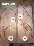
The two rear sections are reverse loops.
I did it this way as the trains are turned at each end Fairford and oxford, so it would be slightly more realistic versus a loop around the back.
One mistake I made was the trains leave Fairford and that should be the largest rear board, as it stands the largest board represents oxford junction. But shhhhhhh!
Nobody needs to know!
(More to follow)
And it’s quite exciting!
I forget the version number but we went around and around several times to end up here.
This stage would likely not have happened without your help.

Here is the table plan, a collapsible 5 element table top.
The main display which is Brize Norton station on the Fairford branchline.
Thanks again to Martin loader for permissions to use his imagery. A source that allowed an idea to seed!
Without his work, I’d be building something else!
The two grey sections clip on to extend the main board from 7 to 9 foot, I did it this way as 8ft (per stock board) would not stand up in my house.
The two rear sections are reverse loops.
I did it this way as the trains are turned at each end Fairford and oxford, so it would be slightly more realistic versus a loop around the back.
One mistake I made was the trains leave Fairford and that should be the largest rear board, as it stands the largest board represents oxford junction. But shhhhhhh!
Nobody needs to know!
(More to follow)
And it’s quite exciting!
Re: Bampton and Brize Norton ca.39-45
Looks good - very nice arrangement. Look forward to seeing more. R-
Young at heart. Slightly older in other parts.
-
AviatorAtHeart
- Posts: 44
- Joined: Sat Jan 12, 2019 7:23 pm
- Contact:
Re: Bampton and Brize Norton ca.39-45
There is more!
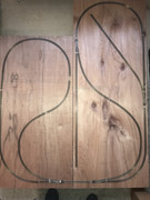
As part of the design, the rear board 5x2 foot has two sidings, each switched from the panel for temporary D.C. operations. This board served as a testing ground for my first train (longmoor farish n gauge) which I am still excited with.
The other rear board is a simple loop but it can (or will be able to) connect to the 4x2 board giving me essentially a folded dog-bone loop or something close anyway!
Each reverse loop section of track per board is controlled by a full wave rectifier....basically four diodes arranged that no matter what way the controller is set, direction of travel is always the same. This has a limitation in that you can only enter the loop from one direction but it simplifies running. All you need to do is turn the exit point and switch the controller. No need to stop the train.
Automating point work is the next thing to deal with!
The exciting bit!
And it took me a while to realise and then break down into its component circuits all the various systems under a layout! Wow.
There is more going on than you realise!
(You being me who is an absolute novice who until only recently knew a total of zero about any of this train malarkey.)
Pic to follow shortly.
Edit.....
Both rear boards will fit together as shown.
This gives me a 5x4 set that allows running without the space for (or completion of!) the main display!
Some mods to both boards may occur that will allow making/breaking and storage of stock etc.
Some more points in the post somewhere down the line!
Each board to be named;
Fair(ly near)ford and (far from) oxford!
One thing I have realised, there is a lot of sideline silliness in even the most professional layout. So that is a start from me to keep inline with those before me!

Re: Bampton and Brize Norton ca.39-45
A most remarkable track plan; never seen the likes of that arrangement before.
A folded dog bone, to be sure, but not in that arrangement. By having two
adjoining reverse loops- is this to increase the operating potential? As a
DCC affair, this could keep the engineer(s) on their toes.
A folded dog bone, to be sure, but not in that arrangement. By having two
adjoining reverse loops- is this to increase the operating potential? As a
DCC affair, this could keep the engineer(s) on their toes.
-
AviatorAtHeart
- Posts: 44
- Joined: Sat Jan 12, 2019 7:23 pm
- Contact:
Re: Bampton and Brize Norton ca.39-45
Thanks all, for the positivity!
I think this looks the way it does is for realism of operations. The fact? it’s not been seen before is probably due to the fact I haven’t spent a lifetime on train modelling! Just doing it my way with all the help I can get!
But I follow no convention as I don’t know any better!
I am an aviation model maker, mostly 1/72 ww2 RAF stuff but I dabble in all sorts occasionally.
Only a short section of each board is a reverse loop electrically speaking. This keeps the electric flow of the track on the main display board free of any complication.
Or at least that’s how I’ve worked it out!
I have learned a bit from the few shows I’ve attended. Most things really apply to the behind the scenes areas, most layouts I saw had 2/3rds more going on behind the scenes! When I first planned this, with no idea of actually how big things were (eg track, locos etc.) it was a 5x3 display with the loop folding around and below the display but that fell apart fast when, thanks to good advice, you take into account a turning circle free from trouble. Minimum recommended radii was a real factor to the size of the back boards, a map I found which allowed me to overlay my track plan also helped define the overall size, along with what I could sensibly keep in a stored position.
Reverse loops;
Main display;
Shown at 8ft board but I had to knock a foot off the western edge due to practicality!
(An image I found online airfield from the air ca.43)

I think this looks the way it does is for realism of operations. The fact? it’s not been seen before is probably due to the fact I haven’t spent a lifetime on train modelling! Just doing it my way with all the help I can get!
But I follow no convention as I don’t know any better!
I am an aviation model maker, mostly 1/72 ww2 RAF stuff but I dabble in all sorts occasionally.
Only a short section of each board is a reverse loop electrically speaking. This keeps the electric flow of the track on the main display board free of any complication.
Or at least that’s how I’ve worked it out!
I have learned a bit from the few shows I’ve attended. Most things really apply to the behind the scenes areas, most layouts I saw had 2/3rds more going on behind the scenes! When I first planned this, with no idea of actually how big things were (eg track, locos etc.) it was a 5x3 display with the loop folding around and below the display but that fell apart fast when, thanks to good advice, you take into account a turning circle free from trouble. Minimum recommended radii was a real factor to the size of the back boards, a map I found which allowed me to overlay my track plan also helped define the overall size, along with what I could sensibly keep in a stored position.
Reverse loops;

Main display;
Shown at 8ft board but I had to knock a foot off the western edge due to practicality!
(An image I found online airfield from the air ca.43)

-
AviatorAtHeart
- Posts: 44
- Joined: Sat Jan 12, 2019 7:23 pm
- Contact:
Re: Bampton and Brize Norton ca.39-45
Exciting stuff!
Electronics or should that be error-tronics!
Rob paisleys designs @ http://www.circuitous.ca/CircuitIndex.html
Along with tinkering about with fiddleyard ideas for the back boards, I thought I’d look into the electronics for the layout. I found robs work and thought I’d use a few of his designs. (That covers what I’ve been doing and not posting about as far as trains are concerned! Along with lots of soldering and learning about electronics as a hobby!)
I did cover the stall motor circuit on the last version of this website, a breadboard Test with video appears in my n gauge Flickr album;
https://www.flickr.com/photos/92891884@ ... 757141774/
I also added his photodetector circuit to the switch part of the circuit. The idea being that if the point has a train on it, you can’t throw the switch!
The main part of this is an LM339 quad comparator ic chip. (A single comparator ic would work for each 556ic, there is one 556 per stall motor driver.)
Simply put, the 339 provides a path to ground depending on the state of the comparator. (Robs site explains all of this, I’m familiar with the 555 timer from other electronics projects, the 556 is basically two 555 timers in one package.)
So I thought I’d add that into the switch, which connects to ground on the stall motor circuit. Now it goes via the comparator. Simple enough idea.......
This board is designed to take 4 stall motor driver circuits.
It is wired so that it breaks the switch path to ground if a sensor is covered. The board allows for reversal, a simple rewire, so it only works when a sensor is covered.
The 556 can sink 200 milli amps, so you could switch several motors from one chip, more or less depending on if you have leds etc. I’m planning on cobalt omega motors which quote 20mA current draw.
This give me an idea for route setting the basic loop on a single switch.
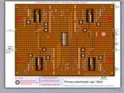
Here is my stripboard version view from the top.
It’s built, tested with leds (which confirms current draw ok.) and as far as I’m concerned is a working test unit.
What follows is a write up of the build warts and all!
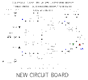

All I have done is feed the switch S1 in the top schematic via the output (goes through led) on the bottom
schematic.
Hey presto. I still need to test a few things.
Most important question.
If several motors are activated by one switch, what load increase appears at the switch. Should be nothing.
But depending on the sink current max. of the comparator could be a limiting factor!
And also, now I’ve built this bit, I’ve realised it’s a lot of work per point! Do I neeeeeeeed it, like really really?
Electronics or should that be error-tronics!
Rob paisleys designs @ http://www.circuitous.ca/CircuitIndex.html
Along with tinkering about with fiddleyard ideas for the back boards, I thought I’d look into the electronics for the layout. I found robs work and thought I’d use a few of his designs. (That covers what I’ve been doing and not posting about as far as trains are concerned! Along with lots of soldering and learning about electronics as a hobby!)
I did cover the stall motor circuit on the last version of this website, a breadboard Test with video appears in my n gauge Flickr album;
https://www.flickr.com/photos/92891884@ ... 757141774/
I also added his photodetector circuit to the switch part of the circuit. The idea being that if the point has a train on it, you can’t throw the switch!
The main part of this is an LM339 quad comparator ic chip. (A single comparator ic would work for each 556ic, there is one 556 per stall motor driver.)
Simply put, the 339 provides a path to ground depending on the state of the comparator. (Robs site explains all of this, I’m familiar with the 555 timer from other electronics projects, the 556 is basically two 555 timers in one package.)
So I thought I’d add that into the switch, which connects to ground on the stall motor circuit. Now it goes via the comparator. Simple enough idea.......
This board is designed to take 4 stall motor driver circuits.
It is wired so that it breaks the switch path to ground if a sensor is covered. The board allows for reversal, a simple rewire, so it only works when a sensor is covered.
The 556 can sink 200 milli amps, so you could switch several motors from one chip, more or less depending on if you have leds etc. I’m planning on cobalt omega motors which quote 20mA current draw.
This give me an idea for route setting the basic loop on a single switch.

Here is my stripboard version view from the top.
It’s built, tested with leds (which confirms current draw ok.) and as far as I’m concerned is a working test unit.
What follows is a write up of the build warts and all!


All I have done is feed the switch S1 in the top schematic via the output (goes through led) on the bottom
schematic.
Hey presto. I still need to test a few things.
Most important question.
If several motors are activated by one switch, what load increase appears at the switch. Should be nothing.
But depending on the sink current max. of the comparator could be a limiting factor!
And also, now I’ve built this bit, I’ve realised it’s a lot of work per point! Do I neeeeeeeed it, like really really?
-
AviatorAtHeart
- Posts: 44
- Joined: Sat Jan 12, 2019 7:23 pm
- Contact:
Re: Bampton and Brize Norton ca.39-45
A quick explanation!

Power goes in on the right side +12V red, 0V black.
Red/black wires follow suit on board, feeding each chip.
Stall circuit wiring purple, green, white.
Each stall circuit repeated in diagonally opposite corners.
Just a slight difference here.
Comparators 1-4, grey, blue, yellow, pink.
Each colour corresponds to one comparator.
Colour code follows legend throughout.
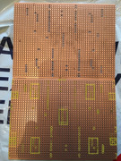
First part and first mistake! Or I thought it was but I made a mistake before this that I didn’t yet know about!
I forgot to mirror my diagram/instructions before I marked the strip board.
So I got it all back to front!
I drilled these holes all the way through, to mark the second attempt! Now I have a hole jig. But it’s a bit of an oops moment!
Transferring marks to the top of the board reveals my error!
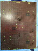
I’m this far out! (Using the jig.....in black)
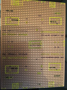
Nice recovery! Correct as it should be.
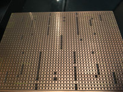
Pins 1 and 13 on the 556 ic chips are not used.
I cut the legs from the sockets so as to preserve the chip.
This is an important step to prevent circuit shorting.
Also need a little tab removing to allow the white wire to pass under the socket.
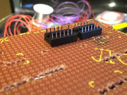
Circuit laid. This forms the test bed.
Bare minimum, just in case!
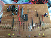
1/4 complete. 5 pairs of pins.
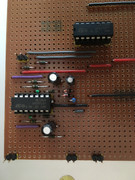
The top pair of pins. Location of 470k resistor.
(This is a variable, sensor sensitivity.)
Bottom row.
Left pair.
Switching output, to motor.
Middle pair.
Left pin 556 switch out. Right pin 339 comparator out.
(Connect both to momentary N.O. Switch)
Right pair.
Sensor out, only one is needed depending on configuration. (+/- input to comparator)
The 5th pair you can’t see is power supply 12V/0V.
Test bed, and the second error reveals itself!
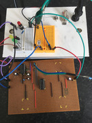
I used 880nm photodiode not visible spectrum! Took me a while to isolate the cause! Minimum order was 5 detectors, so that error willcost more than the fully populated board! (Only approx £5 but in comparison to the cost of this board it is significant!)
I changed the part out for a light dependent resistor. (CDS)
This also meant a change to the 470k resistor.
The circuit works with 3 cds resistors in series.
You just need to adjust the 470k to suit however many sensors you deem necessary.
I have a test video of the complete circuit.
https://www.flickr.com/photos/92891884@ ... ateposted/

Power goes in on the right side +12V red, 0V black.
Red/black wires follow suit on board, feeding each chip.
Stall circuit wiring purple, green, white.
Each stall circuit repeated in diagonally opposite corners.
Just a slight difference here.
Comparators 1-4, grey, blue, yellow, pink.
Each colour corresponds to one comparator.
Colour code follows legend throughout.

First part and first mistake! Or I thought it was but I made a mistake before this that I didn’t yet know about!
I forgot to mirror my diagram/instructions before I marked the strip board.
So I got it all back to front!
I drilled these holes all the way through, to mark the second attempt! Now I have a hole jig. But it’s a bit of an oops moment!
Transferring marks to the top of the board reveals my error!

I’m this far out! (Using the jig.....in black)

Nice recovery! Correct as it should be.

Pins 1 and 13 on the 556 ic chips are not used.
I cut the legs from the sockets so as to preserve the chip.
This is an important step to prevent circuit shorting.
Also need a little tab removing to allow the white wire to pass under the socket.

Circuit laid. This forms the test bed.
Bare minimum, just in case!

1/4 complete. 5 pairs of pins.

The top pair of pins. Location of 470k resistor.
(This is a variable, sensor sensitivity.)
Bottom row.
Left pair.
Switching output, to motor.
Middle pair.
Left pin 556 switch out. Right pin 339 comparator out.
(Connect both to momentary N.O. Switch)
Right pair.
Sensor out, only one is needed depending on configuration. (+/- input to comparator)
The 5th pair you can’t see is power supply 12V/0V.
Test bed, and the second error reveals itself!

I used 880nm photodiode not visible spectrum! Took me a while to isolate the cause! Minimum order was 5 detectors, so that error willcost more than the fully populated board! (Only approx £5 but in comparison to the cost of this board it is significant!)
I changed the part out for a light dependent resistor. (CDS)
This also meant a change to the 470k resistor.
The circuit works with 3 cds resistors in series.
You just need to adjust the 470k to suit however many sensors you deem necessary.
I have a test video of the complete circuit.
https://www.flickr.com/photos/92891884@ ... ateposted/
Who is online
Users browsing this forum: No registered users and 0 guests
