Signaling
Signaling
Hi all,
I think I'm like a lot of modellers, after a lot of trial and error, we come up with a layout that looks good and works well. The next big issue we face concerns signalling, what goes where for the layout design, I'm using coloured light signals.
Can you recommend any books, publications or forums that cover this topic in some detail.
Best Rgds,
Dave R.
Re: Signaling
Signalling is a pretty complex subject and on a model there is usually insufficient space to implement a proper signalling scheme that would be used in real life. Distance between signals can be a major problem. Often a very much simplified system has to be used.
There is a very comprehensive signalling site here https://www.signalbox.org/
There is a very comprehensive signalling site here https://www.signalbox.org/
Re: Signaling
Unless you are a ‘rivet counter’ or know one who will see your layout, you will only need to place home, starter and shunting signals at suitable positions on the layout.
Once you understand how the relative heights of signals indicates priority at points, it’s fairly straightforward to design what is needed in your own location.
You can then, if necessary, introduce a distant or two to give the impression of entering a section controlled by an unmodelled remote signal box.
"Not very stable, but incredibly versatile." 
Re: Signaling
Hi DavidPomDave wrote: ↑Wed Sep 25, 2019 3:01 am Hi all,
I think I'm like a lot of modellers, after a lot of trial and error, we come up with a layout that looks good and works well. The next big issue we face concerns signalling, what goes where for the layout design, I'm using coloured light signals.
Can you recommend any books, publications or forums that cover this topic in some detail.
Best Rgds,
Dave R.
You say your going to be using Colour Light signals, which IMO is probably a simpler choice over semaphore signalling!
What you next need to decide upon is the number of aspect the signals will have. 2, 3 or 4. Personally I would opt for either two and ideally three aspect signalling. 4 aspect involves more signals and can be much harder to replicate reasonably in model form, unless your layout is fairly large.
Approaching a junction where the major route is straight on and the lesser route is the turnout, a Junction Indicator is used (Often called a 'Feather') This normally sits on top of the main signal head and has a row of five white lights indicating the turnout direction is set.
Remember UK signalling has the red aspect closest to the drivers eye line, so with a post or gantry mounted signal the red is at the bottom.
The above link to UK signalling is a great place for information. Some basic signalling can also be found here.. Link to item
Re: Signaling
Hi Guys,
Thanks for your help in this. Living rural in Australia it's not that simple to rush off down to the local train station to pick up some ideas.
I wasn't going to go nuts on signalling, just the basics, but where I get confused is over point work and sidings. Looking at real life pictures and video's I see some lights with a small bar going off to one side or the other and some, 3 or 4 lights, in small ground based ones. I'll certainly look at the links put up and get a better feel for what to do.
Best Rgds,
Dave R.
Re: Signaling
Signals are recognisable railway 'furniture' which add atmosphere to a layout. They are not essential to the working of the model, which will run perfectly well without them, so if you don't put them on the layout it doesn't matter. Your ability to see the train, the track and any obstruction ahead all at once put you in considerable advantage over a real train driver!
However if you put signals on your layout it helps to think about what they do which will help you to place them where they look right.
Signals keep trains apart so one doesn't crash into the train ahead, and trains don't meet each other head on, not really an issue when your track is a continuous loop and there is only one train on the circuit at any given time. However a signal also protects other kinds of conflict such as a train coming off a siding or out of a loop line and being hit by a train on the main line. So there ought to be a signal on the siding and on the main line to stop an approaching train if a conflicting route is set.
The other function of signals is to tell the driver where he is going. Unlike motor cars the driver doesn't steer the train, although it is remarkable how many members of the public still think he does! So the signalman steers the train by changing points and then operates the signal to show which route is set. This is often important because diverging routes may require a reduction in speed from the main route and the driver needs to reduce his speed for safety. On model railways however trains can usually whizz round curves which in real life would throw trains off into the countryside.
Signals for divergences are somewhat complicated because of the mixture of messages they have to convey. A simple turn out will require a simple arrangement, usually a separate arm for the divergence on semaphore signals, or a junction indicator on a colour light (usually a row of lights above the main signal which exhibit a bar of five white lights for the turn off). As more route become possible more arms or light bars are provided, until it gets too complicated when a device which displays a distinctive letter or number is displayed.
Signals for trains running at normal speed are usually large and distinctive visible for up to a mile away. Signals for low speed moves are usually small and close to the ground.
An example of a junction signal is attached. The white diagonal light is used for a diverging route to the left . Trains going straight on don't get the white lights. This is the kind of signal used for trains running at full line speed. The main aspects are red - stop, yellow - prepare to stop at next signal, two yellows - prepare to stop at the signal after next (only used on busy high speed lines) , and green - proceed normally.
A signal for low speed junction, such as for shunting, consists of two lights which are red for stop and two whites diagonally for go.


LC&DR says South for Sunshine
Re: Signaling
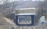
The row of white light in the top picture are actually for a route set off the main line to the right.LC&DR wrote: ↑Fri Sep 27, 2019 9:44 am <Snip>
An example of a junction signal is attached. The white diagonal light is used for a diverging route to the left . Trains going straight on don't get the white lights. This is the kind of signal used for trains running at full line speed. The main aspects are red - stop, yellow - prepare to stop at next signal, two yellows - prepare to stop at the signal after next (only used on busy high speed lines) , and green - proceed normally.
A signal for low speed junction, such as for shunting, consists of two lights which are red for stop and two whites diagonally for go.

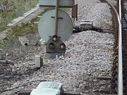
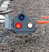
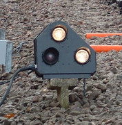
Shunt signals (Position Light Signals or PLS) as shown above are now mainly LED light, but earlier filament lit shunt signals are still seen in some areas. The main difference is the LED lit PLS has a horizontal pair or red lights for On (Stop) and two white lights at around 45 degrees when Off (proceed) the lower pivot aspect on LED signals changing from red to white. Older filament lit PLS had a white Pivot and a red On aspect horizontal and when Off (proceed) the pivot aspect remained white and the upper 45 degree aspect was also lit white meaning Proceed.
Typical Filament lit PLS
Shown On (Stop)

and Off (Proceed)

Re: Signaling
Thank you LC&DR and Brian. Very informative and useful information.
And the Lord said unto John “Come forth and receive eternal life”, but John came fifth and won a toaster!
Re: Signaling
Thank you Brian, I realise I got the feather the wrong way, but it does prove somebody actually reads my posts! 
The GPLs (Ground position light signals) come in a variety of shapes, Early ones were as shown with a white 'pivot' light to the right bottom and red and white for 'on' and 'off' one above each other. A few GPLs had a yellow aspect instead of red which permitted shunts to pass the signal for a move for which the signal did not apply. Typically out of a shunt neck, the 'off' position would be to go out on the main line, and the yellow and white would be displayed for all other moves.
A similar signal was mounted beneath a main aspect which was normally black (out) unless a shunt route was set ahead, when it displayed two white lights diagonally. This might also be a 'calling on' move where a train was permitted to enter the platform ahead while another train is already occupying the platform.
A further use of these shaped signals is as a limit of shunt, which permanently displays two red lights marking the end of a piece of line where wrong direction shunting moves are made. Where passenger trains make a similar type of move, for example a turn back platform normally for 'down' trains but where an 'up' train terminates in it and returns back. The 'Limit' is denoted by a permanently lit fixed red main aspect. Example include Chesterfield Down main.
Back to GPLs, the modern version described by Brian with two horizontal red for stop, and two 45 degree white lights for proceed, was also produced as a four light display, instead of the pivot light changing colour. This was an early attempt to regularise the aspects which could be misleading as originally provided. The red and white normal position could cause a misunderstanding if the red bulb failed and only the single white was showing. The rules did say that a single white light in a GPL should be treated as a stop aspect, but people still did get it wrong. While filament bulbs were being used it was difficult to get them to show different colours, but this is simple with LED technology.
There! My original simplistic reply had subsequently obliged me to make a horrendously complex one all because I got my left and right mixed up!
LC&DR says South for Sunshine
Re: Signaling
Once again I thank you all for your response, I'm beginning to understand what signal lights do and how to use and site them.
Best Rgds,
Dave R.
Best Rgds,
Dave R.
Who is online
Users browsing this forum: No registered users and 0 guests
