Fiddle yard turntable wiring
-
Bandit Mick
- Posts: 908
- Joined: Thu Oct 04, 2018 7:42 pm
- Contact:
Fiddle yard turntable wiring
Many thanks for your replies re: lazy susan. I eventually went with a bolt inserted in the central hole. It works fine and cost me nowt (says the tight Yorkshire man smiling). Sorry to be a pain but another question re: electrical connection. I was going to connect said turntable to the main bus by way of droppers to the tracks. Connection when needed will be via plug in connectors as used for breaks between my baseboards. Now, the question - after a 180 degree rotation I think the polarity will be reversed. So, will I need to provide a connector to each track on the turntable at each end. Sorry about being as thick as the proverbial pig doo dah but when it comes to electrics I'm a bit of a simpleton (as opposed to a simpleton full stop according to my wife). Hope I have explained clearly enough and not confused everyone including myself.
Re: Fiddle yard turntable wiring
A couple of ways to get round it. When you stop the TT you will need to ‘lock’ it in place to ensure alignment - you can use the locks as electrical contacts. Easiest way is a couple of metal tabs connected across the TT joint by bulldog clips.
The expensive way is a reverse loop module that electronically switches polarity when it senses a short.
The expensive way is a reverse loop module that electronically switches polarity when it senses a short.
"Not very stable, but incredibly versatile." 
Re: Fiddle yard turntable wiring
A lot really depends on the number of tracks to be aliened with the main baseboard. Normally this is one or two.
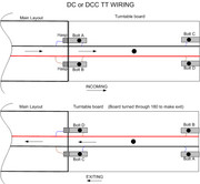
For simplest, and not forgetting you will need to lock the TT in position or you'll suffer derailments at the entrance/exit joints, small brass shoot bolts are used one per rail and obviously the same bolts but not the hasp at the other end too. Simply wire the TT rail to the appropriate shoot bolt each end and the hasp to the rails on the main baseboard (or DCC Bus if you're a DCC user) and when the bolt is across the joint and locking the TT board power to the rails is via the two bolts per track. Open the bolts and the TT becomes dead and nothing can move accidentally. 2" inch or 3" inch brass shoot bolts are normally used. Typical examples ...
Link to 2" bolt or Link to 3" bolt
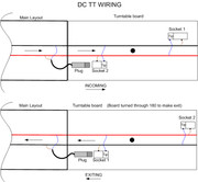
If just one track enters/ leaves the TT board then another method you can use is a 6.3mm (1/4") mono Jack plug and two mating sockets for the TT rail power. The plug is wired via a two core flexible cable to the track rails (or DCC Bus pair) on the main board and plugs into the adjacent Jack socket on the TT, then only one bolt or latch etc is used to lock the TT in position. Example of Jack plug Link to Jack Plug
Example of Jack socket Link to Jack socket
Note: If your layout is DC (Analogue) you cannot use a Reverse Loop Module as these are for DCC (Digital) use only. However, there should be no issues with rail polarity regardless of system used, as you would have to set the direction of travel to enter one way and then reverse it to exit on DC and just reverse the direction of travel on DCC. The wiring of the bolts or Jack sockets to the TT rails would control rail feeding polarity.
Below is the simple wiring using shoot bolts..

Using Jack plug and sockets....

For simplest, and not forgetting you will need to lock the TT in position or you'll suffer derailments at the entrance/exit joints, small brass shoot bolts are used one per rail and obviously the same bolts but not the hasp at the other end too. Simply wire the TT rail to the appropriate shoot bolt each end and the hasp to the rails on the main baseboard (or DCC Bus if you're a DCC user) and when the bolt is across the joint and locking the TT board power to the rails is via the two bolts per track. Open the bolts and the TT becomes dead and nothing can move accidentally. 2" inch or 3" inch brass shoot bolts are normally used. Typical examples ...
Link to 2" bolt or Link to 3" bolt
If just one track enters/ leaves the TT board then another method you can use is a 6.3mm (1/4") mono Jack plug and two mating sockets for the TT rail power. The plug is wired via a two core flexible cable to the track rails (or DCC Bus pair) on the main board and plugs into the adjacent Jack socket on the TT, then only one bolt or latch etc is used to lock the TT in position. Example of Jack plug Link to Jack Plug
Example of Jack socket Link to Jack socket
Note: If your layout is DC (Analogue) you cannot use a Reverse Loop Module as these are for DCC (Digital) use only. However, there should be no issues with rail polarity regardless of system used, as you would have to set the direction of travel to enter one way and then reverse it to exit on DC and just reverse the direction of travel on DCC. The wiring of the bolts or Jack sockets to the TT rails would control rail feeding polarity.
Below is the simple wiring using shoot bolts..

Using Jack plug and sockets....

Re: Fiddle yard turntable wiring
I pivoted my TT on a 1/4” stereo jack plug and socket, which also transmitted power to the bed and in my case powered ledS to indicate the bed polarity. Alignment was by eye as it was powered by a motor-gearbox (rim drive) via a sprung DPDt switch for direction. I could have used an analogue speed control output for both speed and direction.
-
Bandit Mick
- Posts: 908
- Joined: Thu Oct 04, 2018 7:42 pm
- Contact:
Re: Fiddle yard turntable wiring
Thanks for the replies everyone. I think I've got my head round it. Tomorrow is wiring and soldering day.
Who is online
Users browsing this forum: No registered users and 2 guests
