With
Moving Motor Vehicles and Operational Traffic Lights
OVERVIEW:
After recently constructing a large z gauge computer controlled DCC layout without scenery I decided to construct two dioramas to occupy central points within the layout.
The first of the two dioramas was to be a small town site in nature. However, I did not want it to be static. The traffic had to move even if the pedestrians didn’t.
I considered commercially available systems but these were all deemed impractical for z scale operation. It is almost impossible to place motors in z scale cars let alone include rechargeable battery systems. Similarly placing moving chains with magnets in or under the surface of the diorama was not considered practical so this approach was also discounted.
I then came across a system of linear motion being employed by Teeny Trains in the USA. I purchased some of their Connectable track to see if would work for my diorama. It is designed for very small trains and is a single track.
While it worked well for the purpose for which it was designed, that is running one train at a time, it was not able to replicate a two directional roadway with many cars in operation together.
I had almost given up until I came across work being done by Martin Kaselis (www.modelrailmusings.weebly.com). This is all based upon the use of linear motion to move vehicles in a realistic fashion.
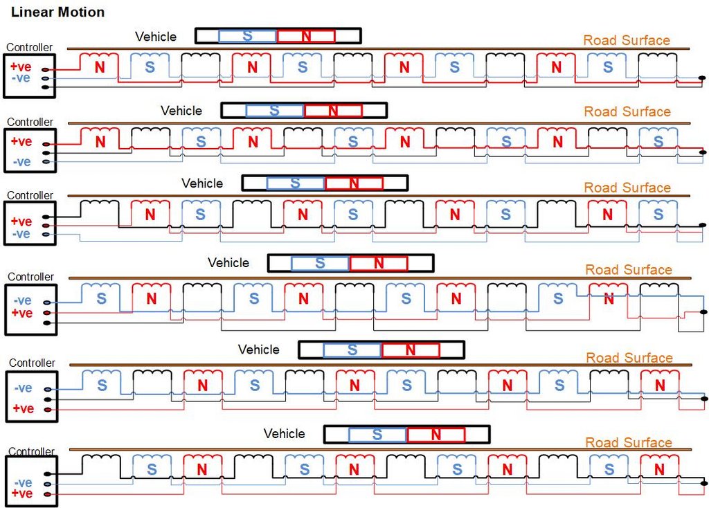
In very simple terms this is how the linear motion functions:
The cars all have powerful permanent rare-earth magnets on their undersides. The magnets are installed such they alternate North and South poles.
The road consists of a series of tiny coils acting as electromagnets. The coils are arranged along the road as three interleaved strings in a repeating pattern As each string of coils is powered in turn the magnets under each vehicle move to position themselves over them.
The coils are always powered so that one string is generating North poles; another string is generating South poles, while the third is off. There are 6 possible combinations of these states, and the controller cycles through them repeatedly.
The following diagrams give an idea of how this all functions.
Using the approach that Martin Kaselis had taken with one of his layouts (Outer Melbourne) where the crossing by cars of a railway line are controlled by boom gates, I decided to have a pedestrian crossing controlled by traffic lights to stop and then release traffic.
The process started with a basic oval shape track as shown in Picture 1 below.
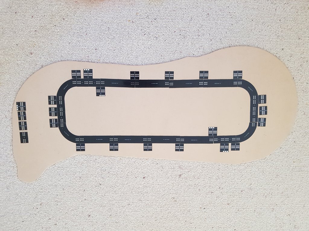
Picture 1.
This shows the individual segments of track and the joiners that are used to connect them. The joiners are soldered underneath the track when it is connected together.
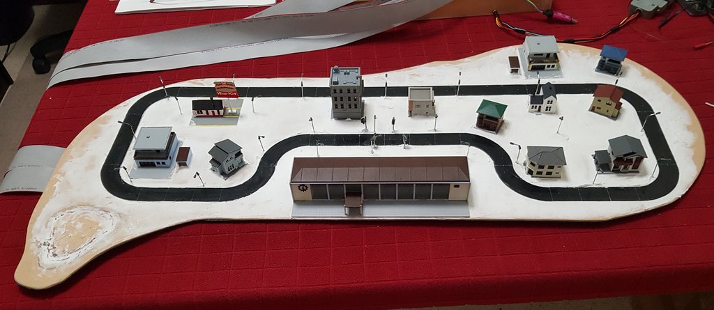
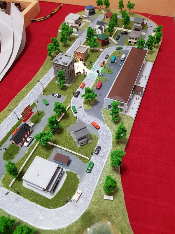
However, the basic oval was too uninteresting so I moved on to that shown in Picture 2 below.
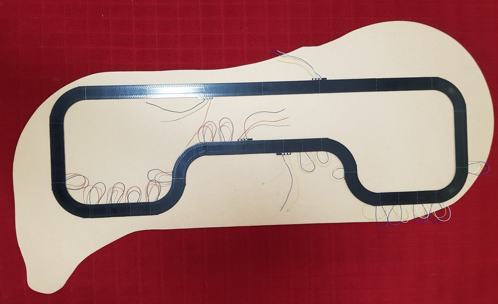
Picture 2.
At the top of this picture, especially in the brightly lit area, you can see the sets of coils embedded in the PC board on each side of the road.
The plan was to have 7 motor vehicles travelling on each side of the road. When the traffic lights turned red, all of the 14 cars would progressively come to a standstill at the lights at the pedestrian crossing. When the traffic lights turned green again the cars would be released in such a way as to provide some realistic spacing between each of them.
In order to turn off segments of the road to hold each of the 14 cars, 120 separate wires are needed to connect to the electronic control unit. In addition to this a further 16 wires are used for the traffic lights and the pedestrian, street and house lighting.
I started the wiring process using separate colour coded cables. However, it soon became obvious that this would be very cumbersome. This is mainly because the control electronics is mounted some two metres away from the diorama. It is alongside the main train computer control boards.
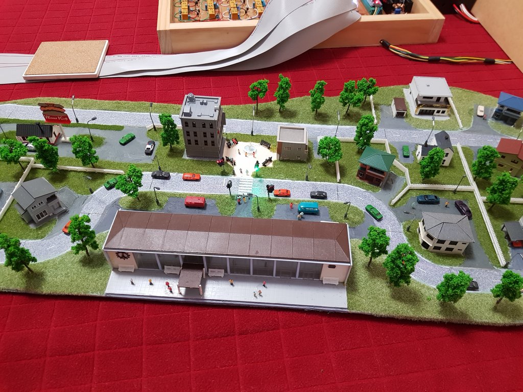
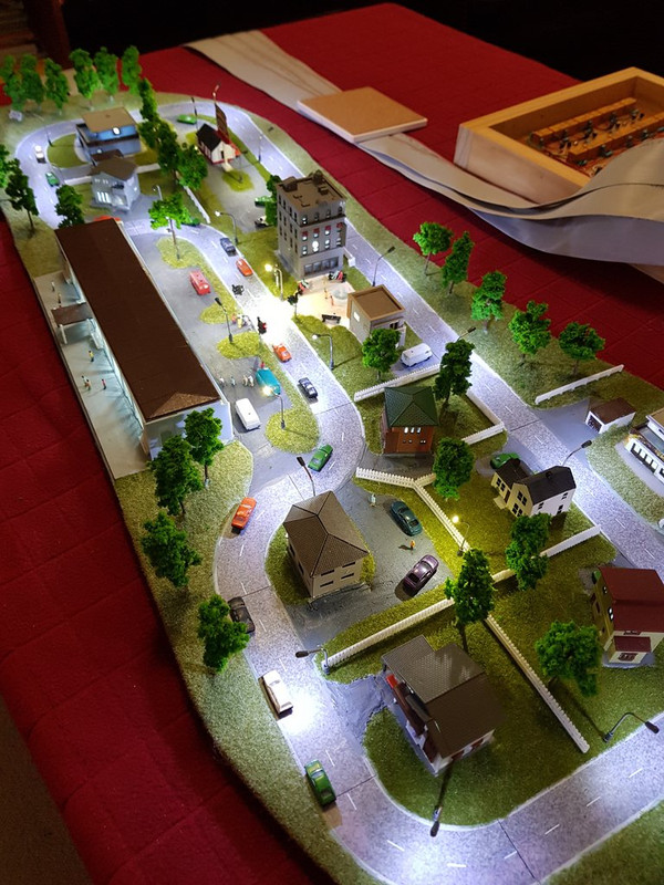
Wiring was then recommenced using 4 lengths of 34 core ribbon cable. These cables can be seen leading away from the left hand side of the diorama in Picture 3 below.
Picture 3.
The real estate is a mixture of USA houses and eatery, Japanese hairdresser, office block and corner café and also German houses. Just your typical town!
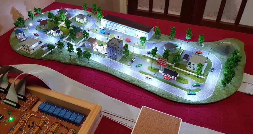
Pictures 4 thru 8 below show a number of views of the complete diorama with the lighting turned off.
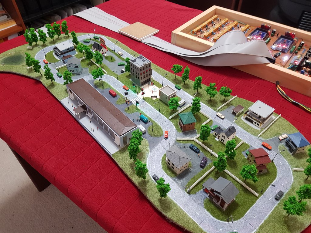
Picture 4.
The Control electronics is in the box at the top right of the picture.
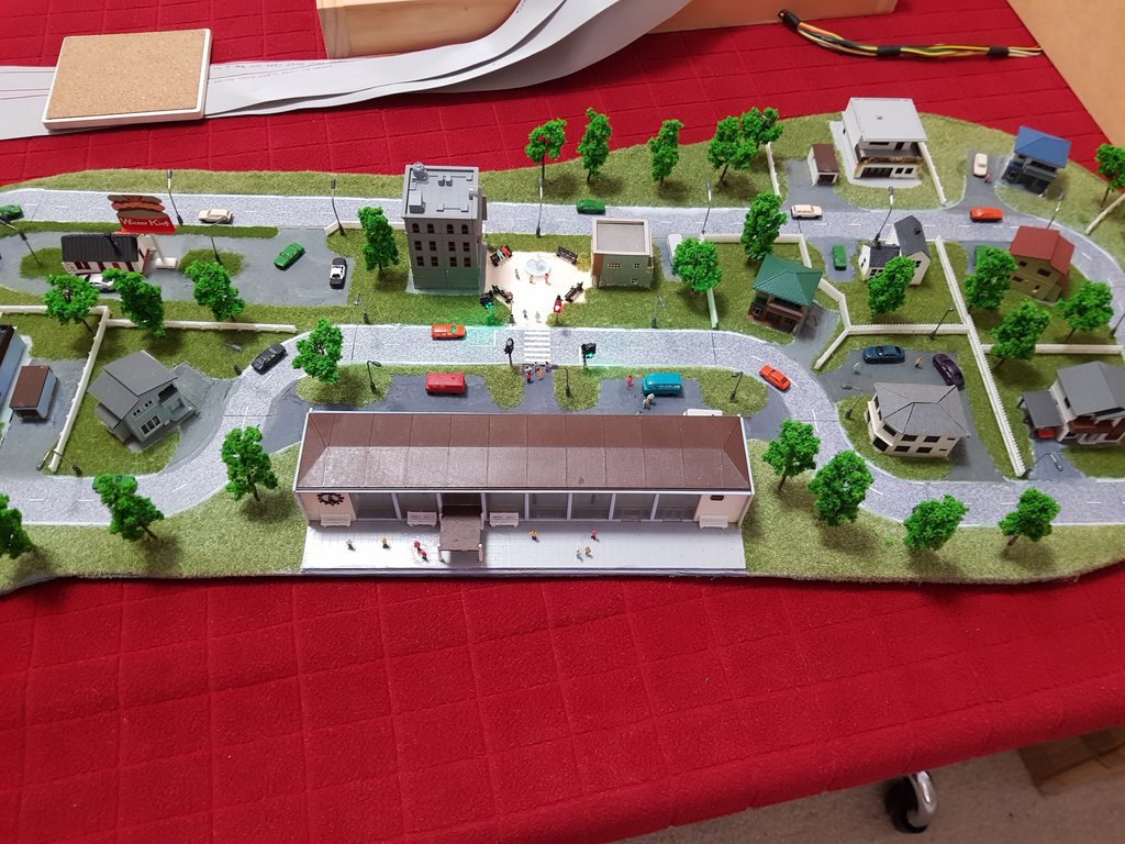
Picture 5.
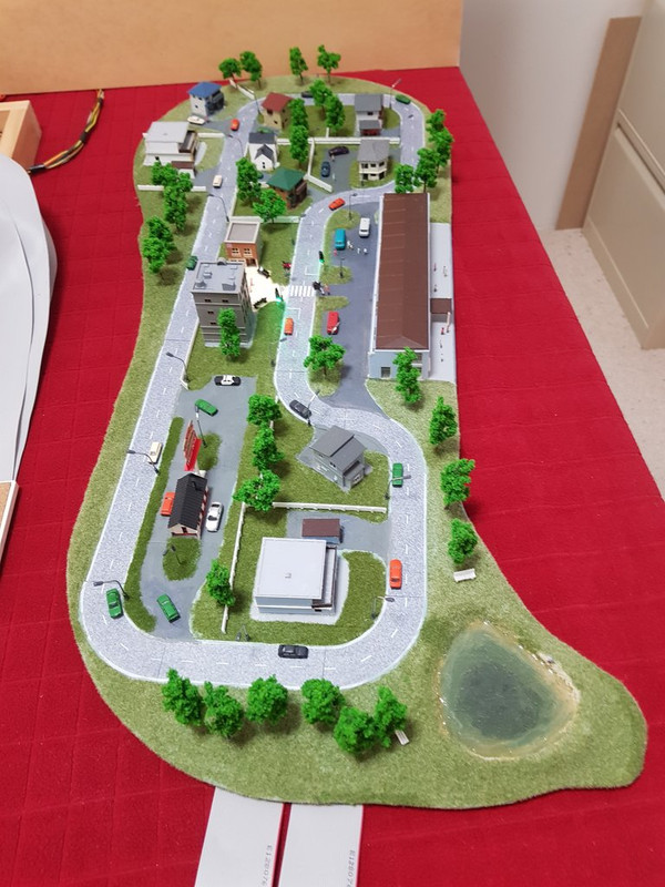
Picture 6.
Picture 7.
Picture 8.
The pictures 9 thru 13 below show a number of views of the complete diorama with the lighting turned on.
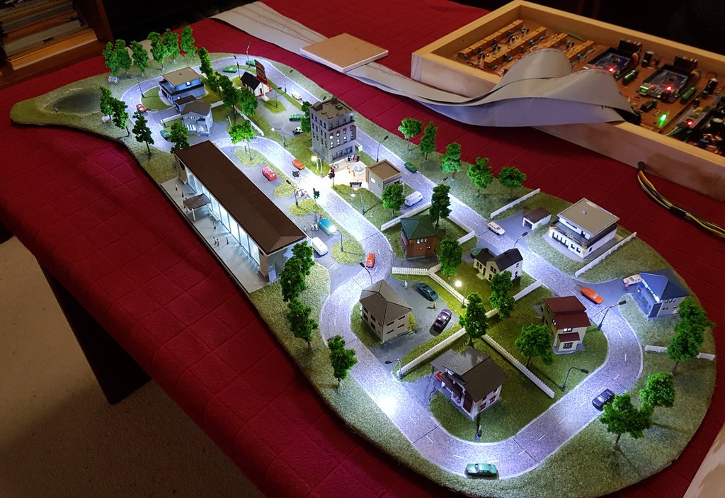
Picture 9.
Picture 10.
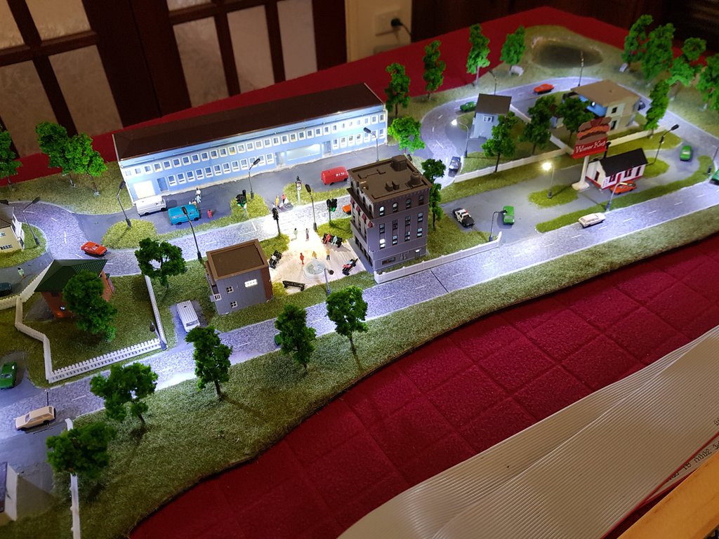
Picture 11.
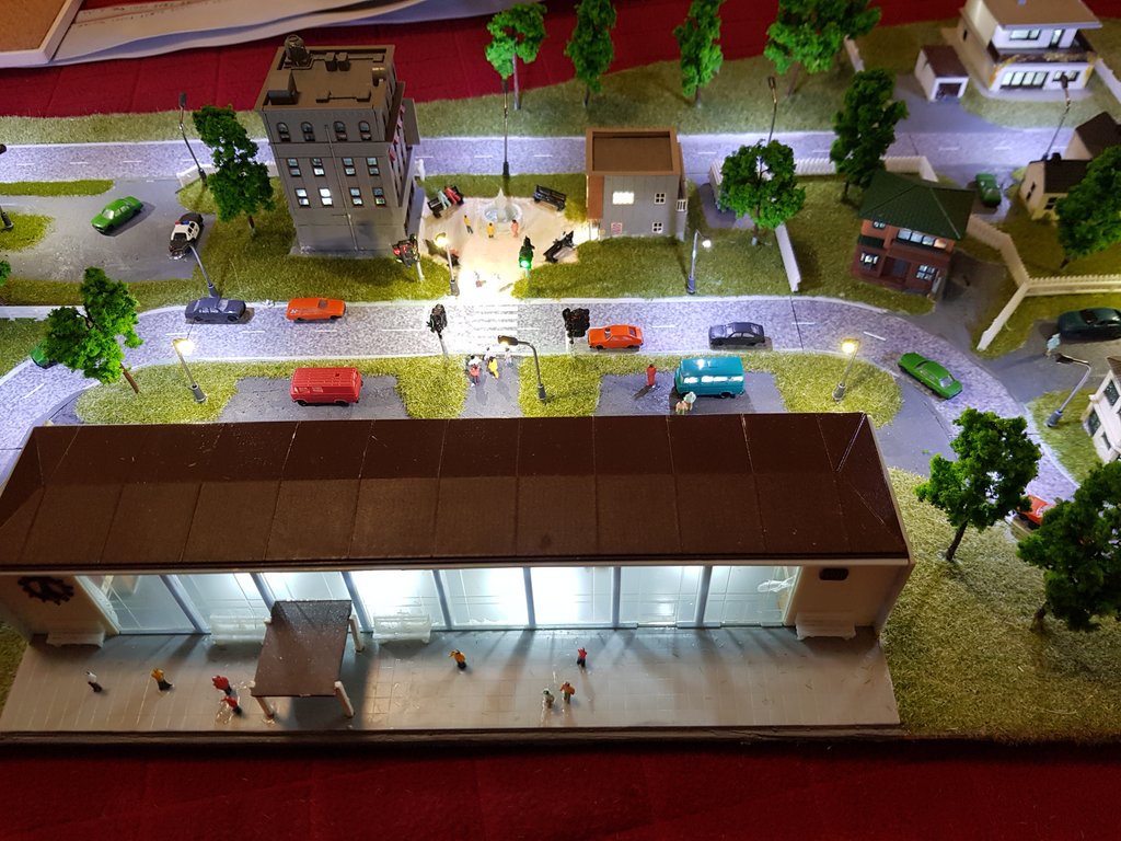
Picture 12.
The cars have come to a halt at the red traffic light. The green light is on for pedestrians to cross the road.
Picture 13.
This picture shows all 14 cars queued at the traffic lights.
Here are two links to short videos that show the diorama in operation.
https://drive.google.com/file/d/1B9BMZ5 ... sp=sharing
https://drive.google.com/file/d/1KvQZe8 ... sp=sharing
For the future: I still have to work out how to make z gauge figures walk across the road!
CONTROL AND ELECTRONICS:
The control of the diorama is best considered as being performed by four separate though interlinked units.
Unit 1: Linear Motion Power Generation
This component generates the 3 phase signals required to drive the linear motion coils that are embedded in the road surface. It runs continuously and has both speed and direction control. The programming of the processor chip used in this unit was undertaken by Martin Kaselis.
Unit 2: Traffic Light Control
This unit controls the operation of the traffic lights. It determines the timings for the signals and provides signals to Units 3 and 4 (described below) to start the queuing of traffic and then its release after pedestrians have finished crossing the road. I have programmed a STM32 processor chip to provide this functionality.
Units 3 and 4: Motor Vehicle Control
These units are employed to queue the cars to allow pedestrians to cross the road and then to progressively release the traffic. One unit manages the inner lane of traffic while the other addresses the outer lane. I have programmed Arduino Mega 2560 chips to provide this functionality. They receive signals from Unit 2 to start their operations.
NEXT DIORAMA:
This is in the early planning stage.
It will possibly be based around:
1 An oil storage facility and depot for loading tanker wagons.
2 A working wind turbine or 2 or 3.
3 A working nodding donkey.
4 A working roadway with fuel tankers and coal dumper trucks.
5 A steam loco re-fueling point.
We will see.