Ground Signal Control
Ground Signal Control
I have recently purchased several DCC Concepts ground signals that I was intended to control using Gaugemaster G500 latching relays (to be activated by the point motors). I now find that the signals only have two wires but the relay has 3 outputs. I have a separate 12v DC power supply for the signals . How should I go about wiring these? Is it even possible ? It is essentially just a matter of using the relay to change the signal polarity but the solution is not obvious to me!
Re: Ground Signal Control
Hi
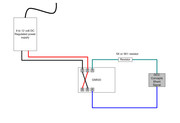
See the wiring below for the DCC Concepts shunt signal and the GM500.
Note:
You MUST fit the resistor (failure to fit it will blow the LEDs immediately)
The power supply should be 9 to 12 volts DC and regulated.
If the shunt shows opposite aspect for route swap wires on GM500 pads 1 and 4
The GM500 cannot be used for any other switching functions i.e. Frog polarity.

Re: Ground Signal Control
Thanks Brian.
How critical that the resistor is 5k ? The shunt signal is supplied with several resistors, 7.5k, 10k and 15k.
How critical that the resistor is 5k ? The shunt signal is supplied with several resistors, 7.5k, 10k and 15k.
Re: Ground Signal Control
Use any of those in that group in place of the suggested 5K..... Suggest you start with the 10K, If the shunt LEDs are are too bright use a higher value resistor if to dim use a lower value.
The DCC Concepts web site quotes a 5K resistor. Rather unusual that they supply three different values. Is there any explanation in the leaflet/manual as to why they do this? e.g. Use xx Ohm value for one specific voltage range and use anther value for a different voltage???
The DCC Concepts web site quotes a 5K resistor. Rather unusual that they supply three different values. Is there any explanation in the leaflet/manual as to why they do this? e.g. Use xx Ohm value for one specific voltage range and use anther value for a different voltage???
Re: Ground Signal Control
They include several different resistance values simply to provide a choice of lamp brightness.
I guess this depends on the period being modelled - for those that are really particular!
I guess this depends on the period being modelled - for those that are really particular!
Re: Ground Signal Control
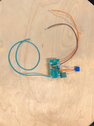
So this is my effort at wiring up each relay - quite a lot of fiddly soldering required!

After fitting four of these to their associated points and signals, none of the relays would work. A careful re-read of the Gaugemaster instructions indicated that when using a CDU power source, the polarity of the input signal is critical. A simple swap of the output wires from my CDU solved this and now everything works as intended.

After fitting four of these to their associated points and signals, none of the relays would work. A careful re-read of the Gaugemaster instructions indicated that when using a CDU power source, the polarity of the input signal is critical. A simple swap of the output wires from my CDU solved this and now everything works as intended.
Who is online
Users browsing this forum: No registered users and 5 guests
