I'm currently looking at the electrical arrangements for the small OO layout which I'm currently building, specifically in relation to point control. Due to space constraints I'm using Setrack points (so insulfrog) and I'm using Peco PL-11 solenoid point motors of (surface mount type - because I have them already from a previous layout).
I'm aware of the conventional method of wiring solenoid point motors, using a 16V AC supply, a CDU, and either passing contact switches or 'stud and probe' arrangement. However when putting together another layout about 10 years ago I came across the attached circuit which uses standard on-on single pole toggle switches instead. I really like it because the toggle switches give a visual indication of the lie of each point, as with a passing contact switch, but at much lower cost. If you use 2-pole switches, the other pole of the switch can be used for polarity switching if using electrofrog points, or (as I'm considering doing on my new layout) to provide a switched feed to the sidings accessed by each point, thus supplementing the connection which is otherwise only provided by the point blade touching the stock-rail. Another possibility would be to use the second pole to switch a remote indicator light, or a simple colour-light signal, or even as an input into a more complex signal interlocking system.
As I say I came across this circuit a decade or so ago and went with it... and it worked really well, but I've ended up having to reverse engineer the control modules I built back then to remind myself how it worked, because it doesn't seem to be a well known method. Does anyone else use it? Are there issues with it which I may not have noticed, which others have found from experience? The only very minor downside which I'm aware of is that because the capacitors only charge with each switch in one direction, it is necessary to switch each point back and forth when first powering on to get them all charged up. But after that, they will all operate correctly. It seems a nice elegant system and I like it. Just checking I'm not missing anythink horrible before I commit to it!
Edit - frustratingly it doesn't seem to want to display the image - I shall endeavour to attach it somehow! Further edit - should be viewable on the link below...
https://1drv.ms/u/s!Al0KteWl_OU5gqhlaNU ... A?e=U0Fuh3
Alternative point motor wiring

Re: Alternative point motor wiring
Nothing new!  It used to be on my web site and is in my book but it causes more issues that it was worth so I removed it from my web site a few years ago!
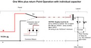
You will need a larger DC power supply than 12 volts and at least 2A or more Amps. This was 99% of the problem. In fact 19 volts DC is about OK and former laptop power supplies are ideal for the circuit.
Here is my originally published drawing of the "One Wire" operation method.
You will need a larger DC power supply than 12 volts and at least 2A or more Amps. This was 99% of the problem. In fact 19 volts DC is about OK and former laptop power supplies are ideal for the circuit.
Here is my originally published drawing of the "One Wire" operation method.
 << Click the Icon to go to my website
Re: Alternative point motor wiring
Thanks Brian, I didn't think it was 'novel' as such, just that it's a method I've seen very little written about as most people seem to go with the 'conventional' method with stud-and-probe or passing contact switches and a CDU. So I was interested in any practical comments people may have. I can't be 100% sure what power supply I used with it before, I think it might have been an old Scalextric PSU (13.5V DC nominally I think, from memory) though I do have a big variable supply as an alternative. I don't recall the switching being unreliable in any case. The use of an old laptop PSU is an interesting suggestion!
Other than the necessity of a suitable supply, is it generally a reliable method? I was really just worried that there might be a reason for it being unpopular!
Other than the necessity of a suitable supply, is it generally a reliable method? I was really just worried that there might be a reason for it being unpopular!
Re: Alternative point motor wiring
Hi
The main reasons its not that popular are the Power supply has to be large enough. Each solenoid motor has to have its own capacitator and two diodes.
Several users of the design came back to me and reported they had issues with unreliable operation. All these were eventually tracked down to low DC voltage and low current power supplies being used. When increased to 19-22 volt DC they were overcome.
A conventional CDU can use a AC or DC power supply of fairly low current. But this design has to use DC of a reasonable voltage and power output.
You can of course use locking toggle switches with a CDU and have a press button per switch wired in to each of the switches feed from the CDU output positive, but it is not ideal.
<< Click the Icon to go to my websiteRe: Alternative point motor wiring
Thanks Brian
Thinking further about the power supply idea, it occurred to me that I could 'pinch' a supply from the 16V AC feed to the layout which is powering the Gaugemaster controllers. Connecting it to a bridge rectifier gives around 21 V DC, which I can put a big capacitor across to smooth it, and I think that should work ok.
Thanks for the pointer.
Who is online
Users browsing this forum: No registered users and 0 guests