Hornby Class 25

A place to show what you are building, altering, kit bashing etc.
Carl L
Posts: 337
Joined: Sun Oct 14, 2018 6:05 pm
Contact:

Hornby Class 25

#1

Post by Carl L »

In between building a signal box, coaling tower, diesel fueling point, water tower and water cranes for Neptune Street shed yard I might consider this for the work bench;

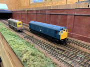
I have just found a Hornby Class 25 which was purchased as a present for me in 1978, so I suspect it may have been Hornby's first production of this model. It has never been run and this is the first it's seen the light of day for decades. For obvious reasons I don't want to part with it.

It will have to be converted to DCC (I couldn't see it on the Bromsgrove models website) and it will have to undergo a repaint in to BR Green in keeping with the era I keep trying to stick to. But I was thinking that there may be some further detailing I could do to improve the model and bring it more in line with today's standards, the front ends look like they could to with some attention. Heavy weathering may also help.

Are there any (super) detailing kits available? I've tried googling this but not found much, apart from an etched roof fan.

Thoughts and ideas would be appreciated, but bearing in mind this will be the first I've attempted this, so heavy kit bashing might be a touch too far.

Carl

Image
User avatar
Steve M
Posts: 3473
Joined: Thu Oct 04, 2018 5:29 pm
Location: Rochester, Kent
Contact:

Re: Hornby Class 25

#2

Post by Steve M »

It looks like most of the ‘detail’ on the model is molded on, so if you plan to upgrade it, you will need to shave and sand the details away prior to filling and more sanding.
I would suggest finding a photo of the real thing on line to work from, and to work out how to replicate the parts. Handrails are easily made from 0.45mm nickel silver wire pushed into small holes. An easy choice for lamp irons would be cut down staples. For lighting try drilling out the holes and filling the holes with Deluxe Glue n Glaze after painting the body.
For vacuum pipes look for an old wound guitar string to make a reasonable copy.
"Not very stable, but incredibly versatile." ;)
Carl L
Posts: 337
Joined: Sun Oct 14, 2018 6:05 pm
Contact:

Re: Hornby Class 25

#3

Post by Carl L »

Steve,

Thanks for the quick reply, coincidental that you mention finding an image of the loco, I've just found exactly that on the Derbysulzers website, in fact several images of it during its life. Seems like it's either a case of Hornby selected this loco because of the website and images or the site selected it due to it's 'celebrity' Hornby status.

But many thanks for the useful tips for detailing the front end. I also think I've seen a flush glazing pack somewhere. Having had another look at the sides and the radiator grills they're not that bad, it would be a lot of faf to file them off and replace, to achieve what? With cosmetics on the ends a respray into green and heavy weathering (and I know where to come for that) I think it should be ok.
vespa
Posts: 34
Joined: Wed Oct 07, 2020 2:04 pm
Location: Cheshire
Contact:

Re: Hornby Class 25

#4

Post by vespa »

Train enthusiast from the 50's. Started with Hornby Dublo.
Carl L
Posts: 337
Joined: Sun Oct 14, 2018 6:05 pm
Contact:

Re: Hornby Class 25

#5

Post by Carl L »

Exactly what I was looking for, thank you.
Carl L
Posts: 337
Joined: Sun Oct 14, 2018 6:05 pm
Contact:

Re: Hornby Class 25

#6

Post by Carl L »

This has just about made it onto the workbench.

I've established it is a good runner on DC, despite being over 40 years old (it was unused).

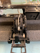
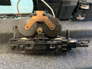
Now to DDC conversion. I've read and read and watched several YouTube tutorials to the stage that my mind is a little clouded. The area of concern is a comment 'There must not be any electrical connection between the left-hand brush strip and the wheels or the metal chassis'. I appreciate that there are several versions of the Ringfield motor. Looking at the attached images can anyone advise if I have any issues, or offer any advice?

Regards

Carl
Image

Image

Image

Image
User avatar
Brian
Posts: 2218
Joined: Thu Oct 04, 2018 3:49 pm
Location: SE Kent
Contact:

Re: Hornby Class 25

#7

Post by Brian »

Hi
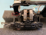
The silver tab on the left hand brush strip is located behind a tab on the metal chassis, this is connecting left strip to metal chassis and wheels. I've marked this with a red arrow on the image. This connection MUST BE REMOVED. Ideally slip a length of heat shrink tubing over the silver brush strip tab to act as an insulator from the metal tab or cut the silver tab off completely. Once removed test with a multimeter set onto continuity or use a buzzer and battery or even a lamp and battery with fly leads to test that the left hand strip is isolated from all motor chassis metal and wheels. If it is proved then continue. If you get a reading, buzz or the lamp lights DO NOT PROCEED and investigate the connection cause and remove it, then retest.

Remove the spade connector on the right hand brush tab and cut it off, this is the wire I've shown arrowed Blue and make an in-line soldered joint with the end of that wire to the decoders red wire. Cover the joint in Heat shrink tubing or use PVC insulation tape over the joint. Cut the white wire or very carefully strip a little of the insulation away exposing the inner copper wire, where I've show the Green arrow. If cut then join the two cut ends back together and to that joint or the area of bared copper connect the decoders Black wire onto it or the joint. Solder the joint and cover the joint with PVC tape or heat shrink tubing. Solder the decoder Orange and Grey wires to the now insulated from wheels and metal chassis brush strips.
Also remove the little brown capacitor that's connected across the two brush strips. Its not needed on DCC.

Position decoder and tidy wiring ensuring it cannot get trapped or foul any moving parts. Test loco on Programming track and set address to whatever is needed. If OK test loco on main track. If it runs the opposite way to the console setting reverse the Orange and Grey wires or use CV29 to alter normal direction of travel.

BTW I would also give the motor copper Comm. a good clean as it looks very black and covered in Carbon from the brushes. Use a soft fibre brush or a cotton bud dampened in Isopropanol Alcohol (IPA) or Meths. DO NOT USE anything abrasive on the Comm. Also worth check is the condition of the two carbon brushes and replace them if badly worn - Spares are available, Peters Spares is one such supplier and even eBay has sellers too.
Image
Image << Click the Icon to go to my website
Carl L
Posts: 337
Joined: Sun Oct 14, 2018 6:05 pm
Contact:

Re: Hornby Class 25

#8

Post by Carl L »

Thank you for the reply, whilst I thought there were issues with the motor I wasn't sure how. That provides perfect clarity.

On the work bench it goes (after some gardening :( )

Regards
Carl L
Posts: 337
Joined: Sun Oct 14, 2018 6:05 pm
Contact:

Re: Hornby Class 25

#9

Post by Carl L »

Apologies for seeming a bit needy with this one, but with electrics I'm at the bottom of a very steep learning curve.

As per the previous reply I have now removed the silver tab on the left hand brush strip which locates behind the tab on the metal chassis.

Image

Using a Lap multimeter I've tried to check
for continuity between the left hand brush strip and the wheels and the strip and behind the tab on the chassis where the silver tab sat.

As I say I'm far from and expert, so these are the images of the meter set to continuity (I hope) and proving continuity to show (me) a reading

Image

Image

So checking for continuity between the left hand brush strip and the wheels this is the reading ( hard to see but the black probe in on the wheel)

Image

And with the probe behind the lug and the other on the strip I get reading anynwhere fron 600's to 1300's (haven't got enough hands to take an image!).

Is the left hand brush strip isolated from the motor chassis metal and the wheels? Or do I still have continuity. I'm a touch confused.

Almost at the point where I wish I'd sent it away.......
User avatar
Brian
Posts: 2218
Joined: Thu Oct 04, 2018 3:49 pm
Location: SE Kent
Contact:

Re: Hornby Class 25

#10

Post by Brian »

Your meter is switched to Buzzer If no buzz is encountered then all is fine, but If the meter does buzz then there is still a connection!
Between the two brush strips you are reading the motors Comm coil resistance. Not an reading needed

You only test needed is ... Left hand strip to all wheels and motor metal. No buzz should be heard. :D
Image << Click the Icon to go to my website
Post Reply

Who is online

Users browsing this forum: No registered users and 1 guest