I’m going to throw my point Roding out of the window!
-
Bandit Mick
- Posts: 908
- Joined: Thu Oct 04, 2018 7:42 pm
- Contact:
I’m going to throw my point Roding out of the window!
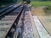
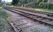
Does anyone know of a way to use Wills point rodding simply but so that it looks something like? I have set up three different height downset drive joints and crank clusters but when I mount them on their corresponding bases, because the bases are different heights they don’t then match up to the point rodding ie some are higher and some are lower. The instructions are poor for someone who is not familiar with the prototype but even with the best will in the world I can’t get them to match up. Also, does someone know the distance from the rodding to the rails/sleepers? The more runs of rodding I use, the further from the sleepers they become (my maximum number of runs one way is 3 just like on the Wills picture). Any help would be welcome before I throw them through the window and go down the pub!
Re: I’m going to throw my point Roding out of the window!
I used the Wills rodding on my previous layout. It’s not really designed to follow any track curvature and although I got it to look OK in the end, it’s overscale and works out quite expensive.
I took a different route on my latest layout and bought cast white metal rodding chairs and plenty of 0.5mm brass rod ( I found a supplier of 1m lengths). That was bent to shape to simulate rodding going round corners and changes of height then I glued etched brass cranks as a cosmetic exercise.
It sounds excessive but it proved easier and cheaper than the Wills version.
"Not very stable, but incredibly versatile." 
-
Mountain Goat
- Posts: 1559
- Joined: Fri Oct 05, 2018 12:57 pm
- Contact:
Re: I’m going to throw my point Roding out of the window!
What make of point levers are designed to go with the rodding?
Budget modelling in 0-16.5...
Re: I’m going to throw my point Roding out of the window!
It’s non-functional, cosmetic rodding.Mountain Goat wrote: ↑Sat May 14, 2022 3:32 pm What make of point levers are designed to go with the rodding?
"Not very stable, but incredibly versatile." 
-
Bandit Mick
- Posts: 908
- Joined: Thu Oct 04, 2018 7:42 pm
- Contact:
Re: I’m going to throw my point Roding out of the window!
Thank you Steve. Looks like I’ll have to simplify my approach. Any idea re: how close to the rails the point rodding should be set?
- Walkingthedog
- Posts: 5023
- Joined: Thu Oct 04, 2018 5:51 pm
- Location: HAZLEMERE, BUCKS.
- Contact:
Re: I’m going to throw my point Roding out of the window!
As Brian said, fit it to suit your layout. I just made sure it would not foul any rolling stock or a track rubber.
"Not very stable, but incredibly versatile." 
-
Bandit Mick
- Posts: 908
- Joined: Thu Oct 04, 2018 7:42 pm
- Contact:
Re: I’m going to throw my point Roding out of the window!
Thank you for your replies. Much appreciated.
Re: I’m going to throw my point Roding out of the window!
Ah, so that's how you did it! What kind of radius wild be the minimum to still look effective?Steve M wrote: ↑Sat May 14, 2022 2:26 pm I used the Wills rodding on my previous layout. It’s not really designed to follow any track curvature and although I got it to look OK in the end, it’s overscale and works out quite expensive.
I took a different route on my latest layout and bought cast white metal rodding chairs and plenty of 0.5mm brass rod ( I found a supplier of 1m lengths). That was bent to shape to simulate rodding going round corners and changes of height then I glued etched brass cranks as a cosmetic exercise.
It sounds excessive but it proved easier and cheaper than the Wills version.
Re: I’m going to throw my point Roding out of the window!
Simon, the question of whether it looks ‘right’ is subjective. After all, the radii used for model curves is nothing like the real world and by definition, the rodding has to follow the track layout.Simon_100 wrote: ↑Thu Sep 01, 2022 12:18 amAh, so that's how you did it! What kind of radius wild be the minimum to still look effective?Steve M wrote: ↑Sat May 14, 2022 2:26 pm I used the Wills rodding on my previous layout. It’s not really designed to follow any track curvature and although I got it to look OK in the end, it’s overscale and works out quite expensive.
I took a different route on my latest layout and bought cast white metal rodding chairs and plenty of 0.5mm brass rod ( I found a supplier of 1m lengths). That was bent to shape to simulate rodding going round corners and changes of height then I glued etched brass cranks as a cosmetic exercise.
It sounds excessive but it proved easier and cheaper than the Wills version.
On my layout I tried to keep my curves as gentle as possible, with the outer curve being just larger than R4, but as my station is on a sweeping curve the tracks get increasingly tighter. My rodding runs alongside those curves and matches their radii as a result.
In the MPD, the rodding follows the inside curve of the medium radius points.
It all gives the impression of rodding but determining if it is ‘right’ is down to the judgement of the viewer.
I suppose it comes down to if it looks right, it is right.
 20220901_094445 by Steve Mumford, on Flickr
 20220901_094414 by Steve Mumford, on Flickr
 "Not very stable, but incredibly versatile." 
Who is online
Users browsing this forum: No registered users and 0 guests


