My son has just bought an old Intercity Class 43 from eBay and we'd like to add a decoder chip.
Looked at some YouTube videos, however it seems this one has been tinkered with already, so I'm not sure how to wire up.
Any advice please?
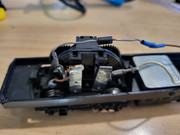
I assume Grey/Orange onto where the spade connectors are and red onto the white cable, but where do I wire the black to? There appears to be an added wire and solder underneath and the other connector is for the bulb. (which we'll probably replace the the RGB board)
Hi
Firstly remove all wires from both silver coloured brush strips, remove the soldered on added wire too. Then with a multi meter set to continuity or use a battery powered buzzer or a battery and suitable bulb, test that the left-hand silver brush strip has no connection to any of the power bogies wheels or to the motors metal work, If there is a connection the cause of the connection MUST BE REMOVED BEFORE connecting a decoder. Failure to test and there is a connection will result in immediate decoder total failure!
Once the left strip tests clear of any connection to the wheels or motor, solder the decoders Grey and Orange wires to the silver strip tabs.
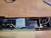
Make in-line soldered joints by connecting the decoder red and black wires to the two wires (Brown and White) that come from the unpowered bogie, remove the blue joints. Removing the spades and the in-line choke too. Cover the in-line joints with PVC tape or better is to use heat shrink tubing applied before soldering the joints then slide down over the joint once cooled and shrink the tube over the joint.
Place decoder in a suitable position ensuring it cannot touch or short onto anything, including the metal weight! Tidy all wiring. Place loco onto the Programming track and alter its address number from 03 to whatever is needed. Once new address number is set place loco onto the main line and test under full DCC power. If the loco runs the opposite way to the console setting reverse the two wires on the silver strips (Grey and Orange wires). Once all is tested OK, refit locos body.
NOTE: When considering a conversion of any older loco, it must run faultlessly on DC rail power before any conversion is considered. Poor DC running will only result in a loco that runs far worse on DCC, if it runs at all!
The brown wire with the choke currently just powers the light by the looks of it (loops round to the rear bogie). Should I solder the black dcc wire to that lump of solder that the copper wire is attached to instead? Unlike other videos I've seen, there is no spade connector in the middle of motor.
So it would be:
Grey and orange on the strip taps
Detach white spade and solder to red
Remove copper wire from blob and solder black to it?
(removing brown and blub altogether, ready for the rgb board from redcat)
Ah... A light isn't visible in the two pictures, I thought the Brown wire was going straight to the rear bogie wheels on one side, while the white wire went to the bogie wheels on the other side!! The item I said was a Choke is in fact a diode for lighting direction control on DC.
So, you need to still remove all wires from the two motor brush strips, including the home-made connection.
Ensuring there is no electrical connection on the silver left hand brush strip by testing, as I detailed previously by using a multimeter or other means.
Connect the decoders Black wire to either the end of the home-made wire and insulate as much as possible the currently bare wire or better is to unsolder the bare wire and solder the decoders Black wire in its place. Connect the decoders Red wire to the White wire via an in-line soldered joint ideally doing away with the blue covered in-line joint.
I assume the RGB board you mention is a Cl43 replacement light unit? If so then proceed as you have suggested with the light unit once it arrives, you will use the decoders Blue and White and/or Yellow wires. Which is then controlled by the F0 key and will be direction of travel controlled too. White wire is the Headlight and red rear lights when going forward, while Yellow wire is opposite ends Head lamp and other ends red lights when in reverse.
Does the lamp work now? If so, remove the brown wire from the bogie and connect to the decoders Blue wire. The other Brown wire, once the diode and in line joint has been removed form it, connects to the decoders White wire for a Headlight. Then F0 turns the headlight On/Off and it will also be direction controlled and only come on when going forward.
PaulMD wrote: ↑Mon May 09, 2022 11:41 am
I assume Grey/Orange onto where the spade connectors are and red onto the white cable, but where do I wire the black to? There appears to be an added wire and solder underneath and the other connector is for the bulb. (which we'll probably replace the the RGB board)
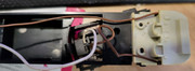
When I've converted ringfield motors the red wire was the one to the left pad on the motor coming from the wheels on the bogie with the motor. That is disconnected from the motor (in your pic it is the bare wire and solder blob). Sometimes the main motor is live and sometimes it is powered from a cable. Either way that should be the red wire to the decoder. The black wire is the wire from the bogie (confusingly white on your model) nearest the light to pick up from the same side as the gears on the motor bogie.
Orange goes to the left pad (as shown in your photo) and grey the other one.
The decoders Red and Black wires can be connected either way around. Conventionally the red wire is the right-hand wheel set and the Black wire to the left-hand wheel set.
The motor bogie with the soldered on chassis wire may be connected to the left or right wheel side?
Brian wrote: ↑Tue May 10, 2022 10:54 am
The decoders Red and Black wires can be connected either way around. Conventionally the red wire is the right-hand wheel set and the Black wire to the left-hand wheel set.
The motor bogie with the soldered on chassis wire may be connected to the left or right wheel side?
This is the power car and the 'front' is where the lights are. The right side would be the side with soldered chassis connection and the left the side with the gears and on the un-powered bogie the left is where the power is taken from.
Many thanks for all the advice, it was most helpful.
In the end, I replaced the ringfield with the DC kit from Strathpeffer Junction and added DCC decoder and Blackcat LED lights.
It's now a fantastic little runner and my little boy is well chuffed.
The bug has got me now and just need to find bogie spares for a Heljan Class 47...