I've just joined the forum, so thought I would give some details of the layout I intend to build.
The overall format is a terminal to fiddle yard end to end, built on 4 baseboards, each measuring 4' x 2' 6".
Track is Peco code 100 and all points will be electrofrog, using DCC for control of locomotives. Points will be operated by servos and it is my intention to have working semaphore signals, also operated by servos. These servos will be driven by MERG modules in an effort to keep wiring to a minimum, but having wired a fair bit already, I'm not sure how successful I have been in this respect.
I hope to include some interlocking on the controls, but this will be limited. A previous layout was fully interlocked, but the number of relays under the baseboards to achieve this was enough to rival an old GPO telephone exchange. Interlocking on the new layout will just prevent a signal being cleard if the correct route hasn't been set.
I don't have any photographs of the progress to date, which is virtuallly all of the track laid and associated wiring, but I will take some over the next few days and update this thread when I do.
Beechmore
-
cheshire lines
- Posts: 403
- Joined: Tue Oct 09, 2018 4:40 pm
- Contact:
Re: Beechmore
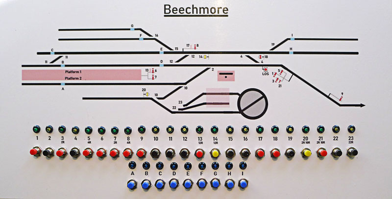
I have just finished putting the buttons and LEDs in the control panel fascia. Next step will be to make a housing and wire it all up.
Last edited by Del57 on Thu Mar 16, 2023 11:29 am, edited 1 time in total.
Re: Beechmore
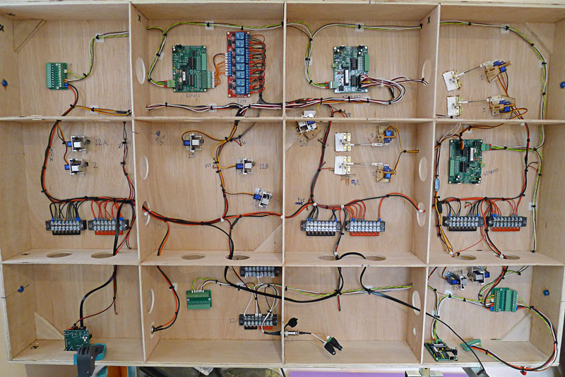
Just for anyone who is curious/interested in what under the boards look like, this is the underside of board 2, which is probably the 'busiest' in terms of wiring and modules. I have still to install the servos for operating the signals, which also need to be installed, so that bit is still some way off.
Last edited by Del57 on Thu Mar 16, 2023 11:29 am, edited 1 time in total.
-
Walkingthedog

- Posts: 5076
- Joined: Thu Oct 04, 2018 5:51 pm
- Location: HAZLEMERE, BUCKS.
- Contact:

Re: Beechmore
Mod NoteDel57 wrote: ↑Sun Feb 12, 2023 1:44 pm Just for anyone who is curious/interested in what under the boards look like, this is the underside of board 2, which is probably the 'busiest' in terms of wiring and modules. I have still to install the servos for operating the signals, which also need to be installed, so that bit is still some way off.
http://www.88qv.com/Beechmore/B2_wiring.jpg
It is a link to a website photo, but the link was placed as an image. I have altered the URL to show the correct URL option {url} v wrongly used {img}
 << Click the Icon to go to my website
Re: Beechmore
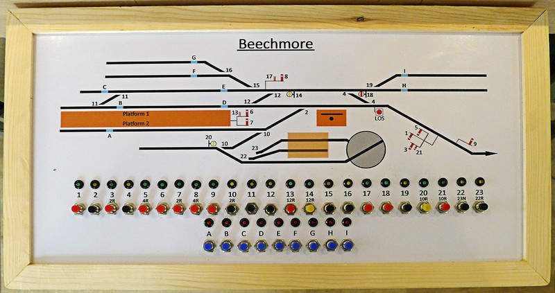
I wasn't happy with how straight I had mounted the buttons on the original panel (I think my jig slipped, and there is a definite dogleg if you know where to look) and I also took the opportunity to amend the colour of the station slightly. I also supplied the printers with a higher res original, so the printing is a bit crisper.
Below is the updated panel, which is now mounted in a box that can be attached to the layout.
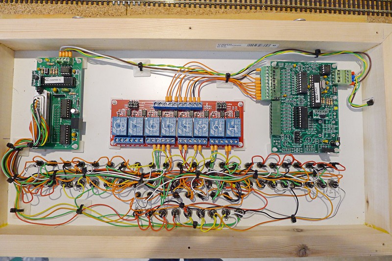
The panel wiring may look a bit involved, but there are 32 buttons and 32 LEDs, so it could actually be a bit worse. Basic wiring at it's minimal would require 32 feeds and a common return to the buttons and the same for the LEDs, so 66 in total between the panel and layout. However, I am using a MERG CANPAN module to handle all the inputs and indications on the panel, so whilst there are still 64 connections to the actual buttons/LEDs this number is reduced to 24 to the module, and this is reduced to just 4 between the panel and the layout; 2 for the 12v power and 2 for the data lines.
The additional modules are a set of relays in the middle, which provide some rudimentary interlocking; basically preventing signals being cleared if the correct route hasn't been set. The module on the right controls the relays.
Below is the updated panel, which is now mounted in a box that can be attached to the layout.
The panel wiring may look a bit involved, but there are 32 buttons and 32 LEDs, so it could actually be a bit worse. Basic wiring at it's minimal would require 32 feeds and a common return to the buttons and the same for the LEDs, so 66 in total between the panel and layout. However, I am using a MERG CANPAN module to handle all the inputs and indications on the panel, so whilst there are still 64 connections to the actual buttons/LEDs this number is reduced to 24 to the module, and this is reduced to just 4 between the panel and the layout; 2 for the 12v power and 2 for the data lines.
The additional modules are a set of relays in the middle, which provide some rudimentary interlocking; basically preventing signals being cleared if the correct route hasn't been set. The module on the right controls the relays.
Last edited by Del57 on Thu Mar 16, 2023 11:32 am, edited 3 times in total.
-
Bandit Mick
- Posts: 908
- Joined: Thu Oct 04, 2018 7:42 pm
- Contact:
Who is online
Users browsing this forum: Goingdownslow and 1 guest