Well, a few months on and I've some more progress to report!
Starting with the control panel.
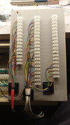
The section switches have been added and soldered, with wiring to the terminal blocks.


A label will be printed, and possibly laminated which will be attached to the panel...

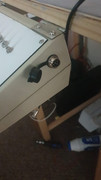
Speed and Direction control will be provided by a GaugeMaster W wired hand unit, which plugs into a new 6 Pin connector on the control panel.
I've gone with D-Sub connectors to connect the control panel to the Distribution Panel, since I don't need to be able to handle more than an Amp through any one circuit. I'm using a 15 way and a 25 way connector. These are quite small, and can be prone to melting the plastic infill as you solder... I always use another socket or plug to secure the connector in place while attaching the wires... this holds the pins/sockets in the correct place if any melting occurs.

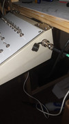
I've assembled two cables which run from the back of the control panel to the distribution panel, and routed these around the back to separate them from wires coming in from the layout boards.


The trackfeeds have been connected together as required, and wired back to the Distribution panel. The theory is now, should I need to, I can disconnect these from the DP and lift the entire layout away from the shelving... should I ever need that to happen. It's not quite as tidy as I would like, but it's a little uncomfortable under there. I'll possibly tidy this up over time. (HA!) The red/orange cable seen is the 16V AC feed from the Gaugemaster PSU.


I hope I've presented these images in an order which makes sense... as i'm happy to announce that I finally have a working railway! The points will remain manual for the time being, but I'll be able to add them one or two at a time without to much work, as I believe i've done all the required ground work for them. The next 'project' is to add the removable shadow station/fiddleyard to the far end of the layout, and also start the scenic work... for now... i'm just going to enjoy 'playing trains'
Rc2 1091 on the move! Piko E69 shunts wagons
(disclaimer - YouTube videos from my channel are not currently monetised. I will advise if this changes in future.)
Father, IT Guy, HO/OO Modeler.