Four Bridges
-
Walkingthedog

- Posts: 4972
- Joined: Thu Oct 04, 2018 5:51 pm
- Location: HAZLEMERE, BUCKS.
- Contact:
Re: Four Bridges
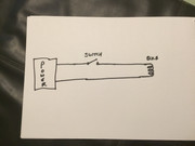
Basically it’s two wires from the bulb to two wires from the power supply with a switch in one wire.
Nurse, the screens!

-
Walkingthedog
- Posts: 4972
- Joined: Thu Oct 04, 2018 5:51 pm
- Location: HAZLEMERE, BUCKS.
- Contact:
Re: Four Bridges
One wire from the bulb through a switch to the power supply. The other wire from the bulb straight to the other side of the power supply.
Nurse, the screens!
-
Walkingthedog
- Posts: 4972
- Joined: Thu Oct 04, 2018 5:51 pm
- Location: HAZLEMERE, BUCKS.
- Contact:
Re: Four Bridges
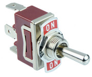
You only need to switch one wire.You just need a simple ON/OFF switch like your house lights.
The switch you have is OFF when in the centre. Then the top tag and left tag are connected when the switch is down, and the bottom tag and right tag (which is hidden) are connected when the switch is up. So if you connect both wires from the bulb through the switch to the power supply, one set of wires will always be OFF and the other ON. When you throw the switch the other way the opposite wires will be ON and OFF. One set of wires will always be OFF and both sets will be OFF when the switch is in the centre position. Wrong switch I’m afraid if you just want the lights On or Off.
The switch you have is OFF when in the centre. Then the top tag and left tag are connected when the switch is down, and the bottom tag and right tag (which is hidden) are connected when the switch is up. So if you connect both wires from the bulb through the switch to the power supply, one set of wires will always be OFF and the other ON. When you throw the switch the other way the opposite wires will be ON and OFF. One set of wires will always be OFF and both sets will be OFF when the switch is in the centre position. Wrong switch I’m afraid if you just want the lights On or Off.
Last edited by Walkingthedog on Mon Jan 14, 2019 5:44 pm, edited 1 time in total.
Nurse, the screens!
-
Walkingthedog
- Posts: 4972
- Joined: Thu Oct 04, 2018 5:51 pm
- Location: HAZLEMERE, BUCKS.
- Contact:
Re: Four Bridges
The switches I have are ON/ON and there is no centre. I was sold these as being ideal for lights but clearly are not so I have just ordered a few On-Off Toggle Flick Switch SPST 12V 25A in the hope they will be ok.
-
Walkingthedog
- Posts: 4972
- Joined: Thu Oct 04, 2018 5:51 pm
- Location: HAZLEMERE, BUCKS.
- Contact:
Re: Four Bridges
In the picture the switch looks to be in the centre, not up or down.
Nurse, the screens!
Re: Four Bridges
WTD - yes it does but in reality, it is up or down. Totally misled by the seller. Anyway, thanks for the information and hopefully once the new switches arrive, I'll be back on track - no pun intended.
Re: Four Bridges
Replacement platform lamps arrived and after wiring one up to test, quickly turned it off as it started to smoke.
These are sold as 12v lamps and are powered by 12v - not very bright either. Back to the drawing board but first back to the seller to complain.
I had a re-think on the panel being used for light switches and decided to go the same design, size etc as the one for the points. Photos to follow.
Sorry if my threads are boring but I hope that what gets written could help someone else one day
Who is online
Users browsing this forum: No registered users and 0 guests