Electricitying points and adding signals
-
Walkingthedog

- Posts: 4972
- Joined: Thu Oct 04, 2018 5:51 pm
- Location: HAZLEMERE, BUCKS.
- Contact:
Re: Electricitying points and adding signals
Just remember to stay low as long as you can. I speak as an expert head banger. 
Nurse, the screens!
Re: Electricitying points and adding signals
You could use the old Hornby controller with the red controller knob, assuming it has a separate 16v Auxiliary AC output, to just feed the point motors?
Yes has seperate power plug, to start with, I'll try just the hm2000 then seperate controller if it stalls too.much, as haven't enough remaining track left to.make a seperate isolated (from main track) track
Steel track, if not kept spotlessly clean and the fishplates are in 100% condition, you will always have poor running!
Yep when I first tested the track on boards on the floor I was having problems. I've since soaked it all.in vinegar and scrubed it down, which has improved it no end. Funnily enough I had one dead curve which was actually nickel.
Currently it's the points that seem to not carry power over reliably, I'm hoping point motors will help sort it, if not I'll add extra power feeds.
Re: Electricitying points and adding signals
So having had a closer look at the switches they're proprietary and take terminal male ends.
Is there any way to make your own or do.i have to buy the ends?
Having had a quick look, the ends are nearly £4 for 10. I would need 27 (3 per switch, 9 switches) so about £12.
I have also found some 2a toggle switches for £8 which would then allow me to use CDU?
Would the toggle switches work or 2a sufficient?
Thanks Andy

Re: Electricitying points and adding signals
Andy, i really would give some thought to a lift out section, now, before its too late. They are dead simple to make, and many of us have them. Much more difficult once track is fixed down, and points/ signals/ masses of wiring, installed. It is so easy to knock all the locos off, or catch an odd wire, whilst trying to enter/ exit, in a hurry. A little time spent now, in planning stage, will repay itself, over and over again, in the future.

Re: Electricitying points and adding signals
Toggle switches MUST be non locking, centre off types. example Ebay link to prevent the point motors from overheating and burning out.
Solenoid point motors such as those from Hornby, Peco or Seep must only be operated for as short a time as possible, 1 second or less. A CDU will provide a very short, high powered pulse to operate them and prevent burn out.
Solenoid point motors such as those from Hornby, Peco or Seep must only be operated for as short a time as possible, 1 second or less. A CDU will provide a very short, high powered pulse to operate them and prevent burn out.

Re: Electricitying points and adding signals
I have replied on the other forum, where some of the advice being offered is perhaps not the best! (Updated as the poster has corrected themselves!) Yes, the pins are expensive and IMO it is not essential to use them. Bared wire end (Soldered if flexible wire) is just as good.AndyH wrote: ↑Tue Aug 04, 2020 9:03 pm So having had a closer look at the switches they're proprietary and take terminal male ends.
Is there any way to make your own or do.i have to buy the ends?
Having had a quick look, the ends are nearly £4 for 10. I would need 27 (3 per switch, 9 switches) so about £12.
I have also found some 2a toggle switches for £8 which would then allow me to use CDU?
Would the toggle switches work or 2a sufficient?
Thanks Andy
BTW. if all the Hornby R044 Black levers are placed together in a bank of levers only one feed wire is needed, as there is a pin on the opposite side of the R044 that connects into the next levers socket and this passes power onto the next Black lever and so on.
Re toggle switches... As I stated in my reply post #2 on page 1 and Rog (RJ) has also highlighted too, they MUST be non locking sprung to centre Off type - Often referenced as (On)-Off-(On) type.
Note if you were to use locking On-On types the coil of the point motor will very quickly burn out as they must only have a very brief pulse of power applied to their coils. A CDU can be used with (On)-Off-(On) toggle switches and only one is needed. Its wired into both supply wires from the power source and its Outputs are usually marked as + and -
The + connection going to all the point operation toggle switches middle tabs. The - of the CDU runs out around the layout and all return wires from the motors connect onto this one wire.
 << Click the Icon to go to my website
Re: Electricitying points and adding signals
Now the next thing for you to consider and ensure when wiring Solenoid point motors, is to use a wire size that's adequate for the motor(s). Do not use so called "Layout Wire" which is frequently 7/0.2mm - its too small!
I recommend for trouble free solenoid motor operation a minimum of 16/0.2mm equipment wire throughout and where two or more motors are to move at once - such as a cross over pair, then consider increasing the return wire size to at least 24/0.2mm or 32/0.2mm (Or even double up two 16/0.2mm wires to make one equivalent to 32/0.2mm!)
I recommend for trouble free solenoid motor operation a minimum of 16/0.2mm equipment wire throughout and where two or more motors are to move at once - such as a cross over pair, then consider increasing the return wire size to at least 24/0.2mm or 32/0.2mm (Or even double up two 16/0.2mm wires to make one equivalent to 32/0.2mm!)
<< Click the Icon to go to my websiteRe: Electricitying points and adding signals
Thanks again Brian.
I have found some terminal ends already crimped to thin cable. As I say it's an old set from a house clearence of a rented property of a relative of mine, which I acquired so never had it set up.
I've just wired one point up which works. I've tried drilling the board to fit it in. What's the best way to do this? It's an MDF board.
In the process I've also managed to dislodge the check rails from the slider on 2 of the points, how can I fix these?
-
Walkingthedog
- Posts: 4972
- Joined: Thu Oct 04, 2018 5:51 pm
- Location: HAZLEMERE, BUCKS.
- Contact:
Re: Electricitying points and adding signals
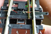
The top left fishplate isn’t connected to the points. It has gone under the rail.
The parts that have come adrift are the switch blades/point blades not the check rails. Can you just pop them back in place.
The parts that have come adrift are the switch blades/point blades not the check rails. Can you just pop them back in place.
Nurse, the screens!
Re: Electricitying points and adding signals
Hi
In reverse.. I'm unable to see the underside view correctly as its not focused - sorry. I think its a Peco PL10 motor? In which case there are four connector tabs - two on one side and two more on the other side. Two tabs on one side are linked together by a wire and a second wire on one of these tabs connects to the motor return wiring. The other two tabs on the opposite side are operation left and right connections from the switch/lever.
If its a Hornby R8014 then it will be pre wired with short wires. The Red and Green are the two operation wires and the Black is the return.
The point with the two switch rails loose/broken away need their D loops placed over the plastic pips. If it holds on all good otherwise you may have to place the end of a flat bladed screwdriver that been heated so as the hot blade melts the very top of the pip fixing it to the switch rails D loop on each side. See the amended image I've attached below.
As the point motor is fixed to the points underside (The four little tabs sticking up through the sleeper slots need bending over or give them a slight twist to lock the motor to the point firmly otherwise it will fall off!) then I would cut a rectangular slot in the board with a jig saw or pad saw after drilling smaller holes for the saws blade, so as the motor drops into the slot. Once the point is correct in place, cut two strips of thin card - post card etc so as the couple of strips cover most of the hole but leaves a slot in the middle for the motors drive pin to move. Glue the card in place each side of the slot onto the top of the baseboard using neat PVA or UHU etc
Note in the top image the rail joiner at the top is not located correctly onto the end of the rail just before the point.
Edit.... WTD beat me to the answers
<< Click the Icon to go to my websiteWho is online
Users browsing this forum: No registered users and 3 guests