Page 2 of 2
Re: HELP PLEASE WITH IRJ & RLM LOCATIONS
Posted: Tue Oct 06, 2020 9:44 am
by The Sligo Rover

Can I fit the IRJ's as placed in the photograph, or do I have to have them in the middle of the crossover track. It would save quite a bit of fiddling about cutting track on the crossovers if I can do them like this.
Re: HELP PLEASE WITH IRJ & RLM LOCATIONS
Posted: Tue Oct 06, 2020 9:54 am
by Brian
They can be at either end of the cross-over track between points, but they should be opposite each other, not staggered as shown.
Re: HELP PLEASE WITH IRJ & RLM LOCATIONS
Posted: Tue Oct 06, 2020 11:14 am
by The Sligo Rover
Brilliant, that means I do not have to cut the crossover rails in the middle. I am glad I asked as that makes it easier, thank you again.
Re: HELP PLEASE WITH IRJ & RLM LOCATIONS
Posted: Wed Jan 13, 2021 12:27 pm
by The Sligo Rover
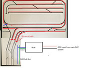
Brian, referring back to your log on 01/10/2020 re the RLM : -
two questions please,
1/ Do I just split the DCC feed from the controller into two feeds, one for my oval, and one via the RLM to by dogleg section if I can call it that?
2/ Either side of the four tracks with insulators on all eight rails, do I keep the polarity from the bus the same please?
I am fitting all my droppers at the moment and just need to clarify please before I go any further which should save me doing it wrong and having to rip it all out again.
Thank you.
Re: HELP PLEASE WITH IRJ & RLM LOCATIONS
Posted: Wed Jan 13, 2021 12:37 pm
by Brian
Hi
1) The feed to the RLMs input needs to come from anywhere that is feed from the main DCC console. If you use a Bus Pair or DCC feed wires then tap off of those. If you rely on the rails to pass DCC around the main layout then tap off the rails somewhere that's feed from the main DCC console.
The input connection onto the RLM doesn't matter which way around the two wires are fitted.
The RLMs output two connections feed all the rails inside the IRJs and all left hand rails connect to one output wire and all right hand rails to the other RLM output wire.
2) When wiring a DCC layout you should always maintain the same main bus wire to the same handed rail throughout the main layout. That is all Outer rails to one bus wire and all Inner rails to the other bus wire. Using the same insulation wire colours for both bus and droppers makes this easier e.g. Red and Black or whatever two colours are chosen. Failure to ensure all same handed rails connect to the one bus wire will result in a full short circuit on the bus and DCC console. So the answer is normally all rails after the IRJs on the main line side should all be to the same bus wire and all opposite sides rails to the other bus. It doesn't matter which way around these are to the Reverse Loops rails, as the RLM will flip the rails to match the main system as necessary.
However, the simplest option IMO on your plan is the need to reposition the left hand tracks pair of IRJs to next to the point as I've shown in Blue line cutting across the track (attached below). A siding will also be included in that section too. Ensure there are no main line DCC feeds on the amended section and the siding. The remaining IRJs a=can all remain as shown or if wished be pushed up more towards the main line point ends. That's up to you.

One thing that needs to be understood is that only one loco/train should enter or leave the RLM section at the same time. That is only ever should one loco/train is permitted to bridge the IRJs at any one time.

You can have as many locos /trains inside the Reverse loop controlled area as you like, but only one must leave or enter at a time.

Re: HELP PLEASE WITH IRJ & RLM LOCATIONS
Posted: Wed Jan 13, 2021 5:05 pm
by The Sligo Rover
Brian, thank you again.
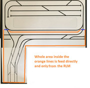
I have noted you blue line as the point to move the IRJ's to, one further question - would it make sense to to the same on the right hand side of my oval, and could I then do away with the IRJ's on the other three lines as shown?
Re: HELP PLEASE WITH IRJ & RLM LOCATIONS
Posted: Wed Jan 13, 2021 5:16 pm
by Brian
Hi
Yes you could do that and everything along the lower front then moves to under the RLMs output.

Amended drawing attached that shows this proposal. The RLM controlled area then becomes quite large, but that shouldn't cause a problem, especially if you use a Sub Bus pair of wires feed by the RLMs output.
The same rule applied though.. Only one train/loco to enter or exit either sides Isolation IRJs at any one time.


