Bournahempton [1936 - Southern Railway - 00 - automated]
-
bulleidboy

- Posts: 2257
- Joined: Thu Oct 04, 2018 6:30 pm
- Location: Basingstoke, Hants
- Contact:
-
jamespetts

- Posts: 67
- Joined: Fri Apr 15, 2022 10:30 pm
- Contact:
Re: Bournahempton [1936 - Southern Railway - 00 - automated]
I use Professional Layout Services. They supplied my N gauge baseboards, and did a good job with them.
-
jamespetts
- Posts: 67
- Joined: Fri Apr 15, 2022 10:30 pm
- Contact:
Re: Bournahempton [1936 - Southern Railway - 00 - automated]
I have recently been working on DCC and coupling fitting one of my two OO Works Adams O4 0-4-2 locomotives. This was not entirely straightforward, as these locomotives are not DCC ready and do not have NEM sockets.
To DCC fit the locomotive, I had to open the tender, use a Dremel with a cutting disc to remove most of the plywood weight, fit in its place a Zimo MX633 and 6.8mF supercapacitor, and replace the single wire from locomotive to tender with a loom of three wires: one for the front pickup and a pair for the motor (the OO Works engines have pickups on one side on the tender and on the other side for the locomotive).
The wires that came pre-soldered to the decoder were not long enough to reach the locomotive from the tender, so I had to solder attach some other wire to increase the reach.
 OO Works O4 by James Petts, on Flickr
I did not have sufficient decoder wire in stock, so I had to use 10/0.1, which was rather bulky, and I had to hide it along one side with heatshrink.
 OO Works O4 by James Petts, on Flickr
I have now ordered decoder wire and will be using this next time; however, this wiring is not as visible as it might be.
I also shortened slightly the tender to locomotive drawbar connexion, as the minimum curve radius on my layout will be 600mm:
 OO Works O4 class by James Petts, on Flickr
OO Works O4 by James Petts, on Flickr
I have also added a Kadee coupling to the rear by removing the supplied tension lock coupling, drilling out the hole with a 2.2mm drill in a pin vice, and fitting a nut and bolt to hold the Kadee coupling in place:
 OO Works O4 by James Petts, on Flickr
 OO Works O4 by James Petts, on Flickr
I have also fitted route discs showing a Salisbury destination:
 OO Works O4 by James Petts, on Flickr
Yet to be done are replacing the generic cabside plate with one bearing the correct number (on order from Narrow Planet), fitting crew and possibly fitting a fall plate.
To DCC fit the locomotive, I had to open the tender, use a Dremel with a cutting disc to remove most of the plywood weight, fit in its place a Zimo MX633 and 6.8mF supercapacitor, and replace the single wire from locomotive to tender with a loom of three wires: one for the front pickup and a pair for the motor (the OO Works engines have pickups on one side on the tender and on the other side for the locomotive).
The wires that came pre-soldered to the decoder were not long enough to reach the locomotive from the tender, so I had to solder attach some other wire to increase the reach.
OO Works O4 by James Petts, on FlickrI did not have sufficient decoder wire in stock, so I had to use 10/0.1, which was rather bulky, and I had to hide it along one side with heatshrink.
OO Works O4 by James Petts, on FlickrI have now ordered decoder wire and will be using this next time; however, this wiring is not as visible as it might be.
I also shortened slightly the tender to locomotive drawbar connexion, as the minimum curve radius on my layout will be 600mm:
OO Works O4 class by James Petts, on FlickrOO Works O4 by James Petts, on FlickrI have also added a Kadee coupling to the rear by removing the supplied tension lock coupling, drilling out the hole with a 2.2mm drill in a pin vice, and fitting a nut and bolt to hold the Kadee coupling in place:
OO Works O4 by James Petts, on FlickrOO Works O4 by James Petts, on FlickrI have also fitted route discs showing a Salisbury destination:
OO Works O4 by James Petts, on FlickrYet to be done are replacing the generic cabside plate with one bearing the correct number (on order from Narrow Planet), fitting crew and possibly fitting a fall plate.
-
bulleidboy
- Posts: 2257
- Joined: Thu Oct 04, 2018 6:30 pm
- Location: Basingstoke, Hants
- Contact:
Re: Bournahempton [1936 - Southern Railway - 00 - automated]
All looks very neat and tidy James - a good job.
-
jamespetts
- Posts: 67
- Joined: Fri Apr 15, 2022 10:30 pm
- Contact:

Re: Bournahempton [1936 - Southern Railway - 00 - automated]
Remarkable, with a tightly defined focus. In North America, a point to point model railway is rare, very rare. The scope of your work makes it even more remarkable. 
-
jamespetts
- Posts: 67
- Joined: Fri Apr 15, 2022 10:30 pm
- Contact:
Re: Bournahempton [1936 - Southern Railway - 00 - automated]
Thank you! Sadly, I have not made much progress on this owing to difficulties in getting the baseboards built. I have been working on my N gauge layout instead. But I do hope to be able to make some progress with this at some point.
-
jamespetts
- Posts: 67
- Joined: Fri Apr 15, 2022 10:30 pm
- Contact:
Re: Bournahempton [1936 - Southern Railway - 00 - automated]
I spoke to the baseboard builder at Warley, who was optimistic that wood supplies had improved to the point where it will be possible to build the layout in the new year.
One issue is how I actually go about laying the track and wiring the layout in light of its position (i.e., on spur shelving around the room at eye level for a standing position and, down the longest edge of the room, above the existing N gauge layout). The issues are: (1) the layout will be high, so laying track will be difficult; (2) the layout will be wide, so reaching the back will be difficult; and (3) the layout will be over the N gauge layout so reaching underneath for wiring will be difficult.
What the person from the baseboard builder suggested was breaking down the layout into modules, laying the track and doing the wiring on these when not mounted to the wall and then fitting these in place.
Below is the track plan showing (in grey) the baseboard join zones (which are wide to reflect the area that needs to be kept clear beneath the baseboards for the joining structures:
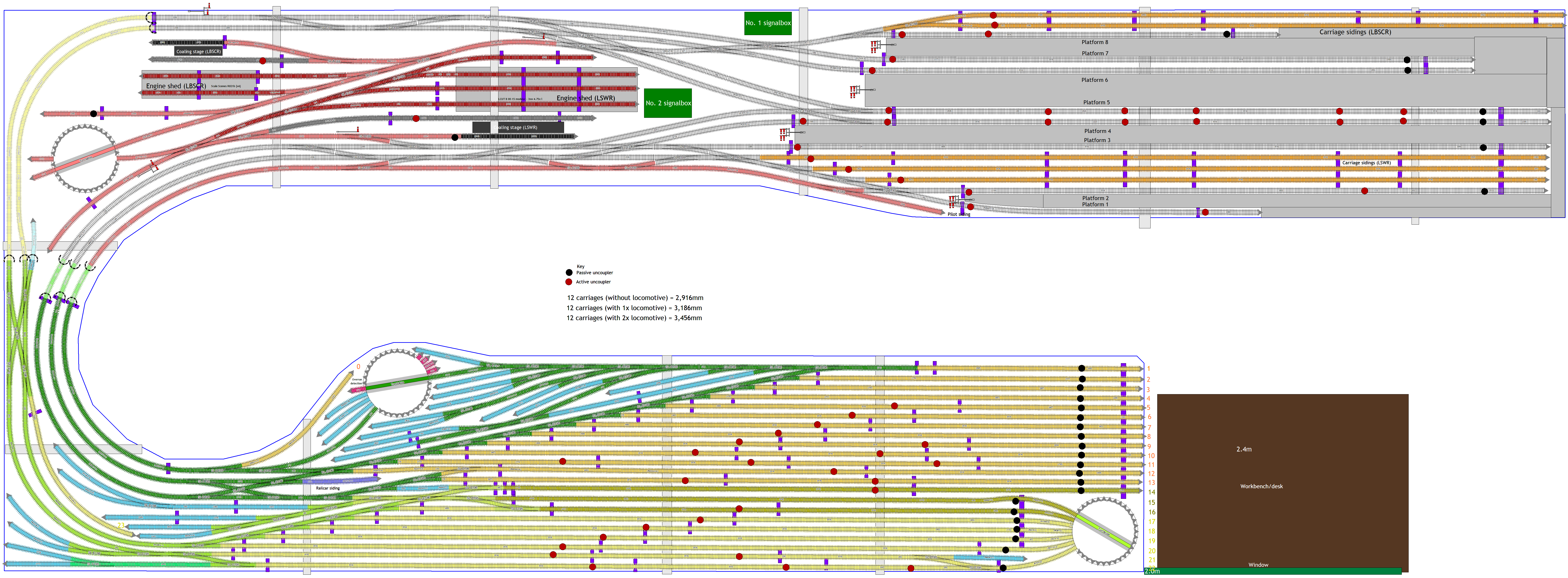
As will be seen, there are (unavoidably) a number of places where there are points or crossings which straddle the joins in one way or another. As this will be a permanent layout, it need not be dismantled regularly, so, as the baseboard person said, it may be acceptable simply to align the plain tracks using rail joiners once the boards are all in place. As for the points and crossings, however, how best to do this is more complex. Presumably, what will need to happen is that, at some point during the build process, one board will need to have part of the turnout hanging over the edge, only to be fixed in when lifted into place and secured on the spur bracket. Presumably, except in the case of crossings, the side that is fixed in place will need to be determined by reference to the need for the toe to have a point motor attached to it.
The next complexity is how actually to lift the boards into place. These are likely to be very heavy, and one slip could cause serious damage to the N gauge baseboards below. I may have to get the baseboard builders to come back once the modules are completed just to fit them.
Another question is signals; these are much more delicate than track, and will presumably need to be added afterwards. They are much fewer than point motors, etc., so it may well be possible to do these with the baseboards in place without excessive difficulty.
Thoughts on the practicalities of all this will be appreciated.
One issue is how I actually go about laying the track and wiring the layout in light of its position (i.e., on spur shelving around the room at eye level for a standing position and, down the longest edge of the room, above the existing N gauge layout). The issues are: (1) the layout will be high, so laying track will be difficult; (2) the layout will be wide, so reaching the back will be difficult; and (3) the layout will be over the N gauge layout so reaching underneath for wiring will be difficult.
What the person from the baseboard builder suggested was breaking down the layout into modules, laying the track and doing the wiring on these when not mounted to the wall and then fitting these in place.
Below is the track plan showing (in grey) the baseboard join zones (which are wide to reflect the area that needs to be kept clear beneath the baseboards for the joining structures:
As will be seen, there are (unavoidably) a number of places where there are points or crossings which straddle the joins in one way or another. As this will be a permanent layout, it need not be dismantled regularly, so, as the baseboard person said, it may be acceptable simply to align the plain tracks using rail joiners once the boards are all in place. As for the points and crossings, however, how best to do this is more complex. Presumably, what will need to happen is that, at some point during the build process, one board will need to have part of the turnout hanging over the edge, only to be fixed in when lifted into place and secured on the spur bracket. Presumably, except in the case of crossings, the side that is fixed in place will need to be determined by reference to the need for the toe to have a point motor attached to it.
The next complexity is how actually to lift the boards into place. These are likely to be very heavy, and one slip could cause serious damage to the N gauge baseboards below. I may have to get the baseboard builders to come back once the modules are completed just to fit them.
Another question is signals; these are much more delicate than track, and will presumably need to be added afterwards. They are much fewer than point motors, etc., so it may well be possible to do these with the baseboards in place without excessive difficulty.
Thoughts on the practicalities of all this will be appreciated.

Re: Bournahempton [1936 - Southern Railway - 00 - automated]
I have two layouts, one on a shelf 18” wide above the other (wider) layout. Both were built as separate modules but I made sure that all the points were a) confined to only two boards and b) were well away from board joints - bear in mind it’s almost impossible to fit underboard motors close to the side and end panels.
It’s a breeze working on a board stood on its side - that’s how I did my wiring for droppers, point motors and mimic board. But there comes a point where you have to leave the boards in situation and work from underneath - for me that was the lighting and the servos for the signals.
My upper layout was completed first but I have found that it is impossible to work under the boards with the lower layout in place - fortunately it is still possible to break that one down for repairs.
"Not very stable, but incredibly versatile." 
-
RSR Engineer

- Posts: 256
- Joined: Sun Oct 07, 2018 11:18 pm
- Location: Freistaat Bayern
- Contact:
Re: Bournahempton [1936 - Southern Railway - 00 - automated]
An interesting-looking layout, James. I take it the LBSCR and LSWR each have their own fiddle yard and that you intend to marshall trains without manual intervention. Are you perhaps intending to reproduce a location like, say, Portsmouth? Two double-track main lines will certainly keep you nice and busy.
About your baseboard joints. On my old layout I had three turnouts that were laid across baseboard joint lines. These baseboards had to be removable for maintenance and access to the tracks underneath. Because I hadn't planned ahead properly and just laid the rectangular boards as they were, I had to cut the points through after laying them in. In two cases there were actually no problems with keeping the rail ends aligned but in one curved turnout (CR2 in the referenced pictures) the cut went through the switch rail, a piece of which was kept in place by two chairs and the feed wire and soon dropped out, not a very elegant solution. And the wiring up was a bit hairy anyway; the tracks beyond the points needed the isolating function.
Before, with old turnout CR2 cut in half: https://www.flickr.com/photos/188026976 ... 904478023/
Afterwards, with new turnout CR2 in place: https://www.flickr.com/photos/53775591@ ... 714966881/
The solution was to reconfigure the board boundaries on the new layout to match the natural joints in the track.
There were also problems where the tracks were cut at a non-right angle. See pics 701 et seq.
https://www.flickr.com/photos/53775591@ ... 4145/page3
I'm publishing this in case it's of use.
Cheers,
Artur
Who is online
Users browsing this forum: Chops, Google [Bot] and 2 guests