Page 3 of 4
Re: DJH model building
Posted: Wed Apr 29, 2020 1:51 pm
by one man and his dog
Thanks to Jim for his kind comments. A positive peer review is very encouraging.
Well I couldn't do much more to the chassis until it was painted so I got on with the body. Very glad I practiced on something cheap first, the body could have gone better but I think it will be useable though a bit of filler will be required where some bits didn't fit as well as they should have and the solder couldn't span the gap. My fault I'm sure and not the kit.
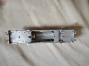
I've included a view of the bottom of the footplate because I think it represents a good lesson learned, I think I should have soldered in some nuts on the upper face of the footplate. The bit that will be an absolute swine to get to now. I'm not going to stress over it, when the time comes if captive nuts are required then I'll get them in somehow.
I decided that before I got on with fixing the wheels I'd get some Peco insulating washers as recommended by Tony Wright in his video. My local shop is sold out and apparently the Peco factory is closed to protect the health of their staff. Can't criticise them for that. So it looks like I may have to be patient but I'm not sure. I've ordered some washers from eBay. Not Peco ones but they may do if I'm really lucky.
Hope you are all keeping well.
Richard

Re: DJH model building
Posted: Wed Apr 29, 2020 2:22 pm
by Walkingthedog
So far so good. Perhaps the closure of Peco etc. is a good thing, stops you/us rushing things.
Re: DJH model building
Posted: Sun May 10, 2020 5:08 pm
by one man and his dog
OK, this is where I am now.
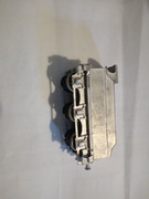
Assembling the 4-4-4 body went quite well though not perfect of course. Apart from the nuts that I have already mentioned, most of the detailing had to be soldered from the outside and would have been better done from the inside but having already assembled the major components that was no longer an option. I also managed to break off one of the spurs, on the front buffer beam, that are supposed to knock debris off the track. Soldering it back on it broke in a second place then the one on the other side broke off. Oh well, never mind. My model will represent one without the front spurs. The last piece of detailing was the Westinghouse pump. Checked that the hole was big enough, tinned the white metal, then tried to place the pump into the solder that I re melted. Couldn't get the pump to go into it's socket so persevered. I'm sure the metal got pretty hot and I pushed quite hard then the footplate broke! See attached photo. At that point I ordered a new kit. At least I won't need the wheels or motor. To keep myself occupied I built the tender to the 0-10-0 which is the real reason I'm building a DJH kit in the first place. One of the last things in the instructions for the tender was to check that all was square. Well I'd been doing my best to keep it square from the outset and there was no advice on what to do if it wasn't square. I don't think mine is perfectly square, if it doesn't run well I may have to remove one of the main frames, file a bit off one end, and reattach. I'll let you know how I get on. I've attached a photo of the tender as well.
Today I started on the 4-4-4 again but decided I needed to get on further with the chassis before deciding exactly where to start with the body. Generally I'm going to try and attach the detail first, the buffer beams with the spurs are going to go on quite late, but I'm going to make more progress with the chassis to make sure I solder on any nuts required on the body. One lesson for anyone else attempting one of these kits. You cannot get the cog onto the axle with the grub screw started. Neither can you get the grub screw started unless you file a surprisingly large flat on the axle. I'd have rather drilled a hole in the axle for the grub screw to seat into but my pillar drill is just too big. The chuck won't accept anything smaller than 3mm which is way too big and I'm not sure I'm skilled enough to get the hole in the right place anyway.
I'll let you know how I'm getting on when I do some more.

Re: DJH model building
Posted: Sun May 10, 2020 10:44 pm
by IanS
All looking good to me!
Perhaps the first attempt can be utilised in a 'scrapyard' a la Glencairns' pics.
Re: DJH model building
Posted: Fri Jan 22, 2021 6:55 pm
by one man and his dog
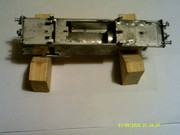
Well after a summer and the autumn off I'm back to modelling again. Here are some of the lessons I've learned since I was last on here. Firstly get some 2 by 1 timber and cut it as shown in the photograph below.

The advantage is that you can then support the model without putting any load on delicate parts. Again, see below.
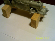
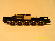
The next thing I learnt is that the chassis is not what I thought it was. The instructions advised assembly of the chassis and painting it before working on the body. I thought I had done that, because I had assembled all the brass bits, however when I got started on fitting the bogies the model then looked like this.

All that white metal should have been painted black at the outset I think.
The next thing I learnt was to check the clearance for the motor. I attempted to put the body on the chassis and it didn't fit, in fact I thought it was unbuildable. After some investigation I found this in the packaging with the motor.
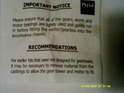
That's got djh off the hook, but I still have to somehow remove the metal that I have coloured black. Not sure how to do it, would have been easy before I assembled everything but now? Perhaps I can chain drill it?

I decided to do something on the Lickey Banker to keep myself cheerful and this is the current state of that model. I wonder if I should have fitted the cylinders before I painted the chassis? I'll let you know.
Happy modelling.
Richard
Re: DJH model building
Posted: Sun Feb 14, 2021 5:00 pm
by one man and his dog
Well I got the excess metal off the body OK, I used a milling machine. Good job I had access to one I think.
So what else has happened? Well I got the crankpins fitted onto the 4-4-4. I wonder how they are supposed to be fitted? I'll tighten them up with pliers but don't grip them too hard, I don't want to mark the metal. Nevertheless, had to clean up the pins with emery paper before I could get the con rods to slide on. Then applied some electricity to see if she ran OK. The perceived wisdom is to remove the grub screw that holds the gear onto the axle and do this by hand, but I was very concerned about getting it back in, in the right place, so used electricity. The whole thing jammed up solid.
What on earth is going wrong? Left the power connected, but not turned up full, while I tried to ease the wheels round and see what the problem was. Very confusing, couldn't see anything wrong at all. Then the motor burnt out. I really don't want to spend £75 on a new motor when I still don't know what the problem was so I think I'll just put it down to experience, but if I was starting again I'd definitely start with a 0-6-0. I'm sure a two axle design required more accurate con rods than a three axle design. One positive did come out of this however, after looking long and hard at the crank pins, I thought there must be a better way to install them, I realised you don't use pliers or a spanner. You use the tool from Romford that is used to assemble the wheels onto the axles. Another expensive lesson learned but at least I didn't mess up the 0-10-0. That would have upset me.
See picture below.
So I went back to the Lickey Banker 0-10-0. Attached the crank pins and the con rods. Loco ran fine. Built up the pistons and they didn't fit. The instructions said, and I quote "Make up cylinder parts (55) through (62)". I did that, you can see them in the next photo.

Re: DJH model building
Posted: Sun Feb 14, 2021 5:06 pm
by one man and his dog
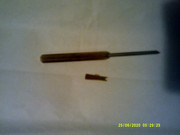
Somehow I managed to post the message before had finished it. One photo shows the cylinders, there was no indication of how far the slide bars were to protrude and yes, I got it wrong. Had to then spend £30 in replacement parts from DJH. The other photo shows a piece of brass supplied by DJH for assembling the wheels and crankpins, good of them to supply it but I purchased the tool sold by Romford and I'm glad I did. It works and no messing.
I'm going to post this message then take up where I left off.
Re: DJH model building
Posted: Sun Feb 14, 2021 5:38 pm
by one man and his dog
So what happened next. Well my replacement cylinder parts turned up and I then ignored the instructions. I soldered the cylinders to the chassis; that's the chassis that I had painted black as per the instructions. I had to file off the black paint to get the solder to take. Another lesson learn't. I then positioned the slide bars onto the motion bracket and soldered them in the correct position relative to the cylinders. I then completed the cylinders. Next the crossheads (pistons to me, but what do I know?) were installed, nobody told me they were too long and had to be cut to length but it wasn't a big deal, just confused me for a while. Then the Connecting rods were installed. The pivot onto the crosshead is an M1 bolt. I soldered the bolt to the con rod and I'm glad I did. It made assembly easier and didn't cause any problems.
Then it was onto the valve gear, now, I had decided that if this was as difficult as it looked I could always run the loco without valve gear, not exactly correct but my first Tri-and train, 1959 vintage, set a precedent. In fact it has gone OK so far except the crank rod that is soldered to the end of the crank pin on the third axle keeps coming off I keep resoldering it. I think it is handling the loco that does the damage not running it. Anyway, onto the assembly of the valve gear. It was very fiddly, the moving parts are riveted together. Sounded like a recipe for disaster to me so I inserted a piece of paper between the parts before riveting them. See photo

This shows the rivet sticking up through the part to be connected though you may have to take my word for it. I then placed a piece of paper over the rivet to act as a spacer. I tried using a piece with a hole punched in it but 2mm was my smallest punch and it didn't work so I just cut a slot and that worked fine.

I then placed the second part over the rivet and hammered over the end, not too hard. Picked up the completed job and it fell apart. Reassembled it and hammered the rivet a bit more. This time it stayed together but seemed very loose, tap tap, pick it up, tap tap, pick it up repeat until it seems a little stiff. Remove the paper and it is free to turn but not too loose. To gain some understanding of what I was trying to achieve I studied Walcherts valve gear on the internet and that made life more difficult not less. The critical difference between the real thing and a model is that on the model, radius rods do not move! You can solder them in place, all will be fine!
Well out of the 12 rivets supplied by DJH I have used 6 for the valve gear on one side, lost 4 and used two to make a start on the other side. I'm now waiting for 12 more 0.8mm rivets from a well know internet auction site so I can continue.
Happy modelling.
Re: DJH model building
Posted: Sun Feb 14, 2021 8:52 pm
by IanS
After reading through all this I am glad I just use ready-to-run locos from Bachmann, Hornby etc!
I couldn't assemble anything like a loco, even in plastic so doing so in metal would be well beyond my skillset (and beyond the skillset I aspire to have).
Keep up the good work and the commentary on the progress. A very interesting thread.
Re: DJH model building
Posted: Mon Feb 15, 2021 10:24 am
by RogerB
Very amusing reading. Some parts have a familiar ring to them, keep us updated. R-