Hornby Dublo 3 Rail

Re: Hornby Dublo 3 Rail
Isolation rail isolates loco on that siding, eg that section of track, following rail is dead. Forget insolation. You only short track, if metal wheel from loco or truck comes into contact with live rail, eg, making a circuit. Same with points. If loco jumps points, same effect. Post a picture of your layout. If you lay it rail by rail, testing with loco, as you go, should be fine. If by changing points short occurs, you have introduced power twice. 3 rail, is fairly simple to lay, but you must ensure, when connecting more than 1 feed rail, that all wires are the same, eg, plus to plus, minus to minus. It is different to 2 rail, in that middle rail is powered. Because track is old, often , rails are not 100 per cent level, when joined. I run a truck by hand over each joint, adjusting level as i go. You will get there, just takes longer than 2 rail.
-
Mountain Goat
- Posts: 1576
- Joined: Fri Oct 05, 2018 12:57 pm
- Contact:
Re: Hornby Dublo 3 Rail
Do you have a second loco to try?
Best way to test track (If it is not pinned down) is to start first with the loco on the power connected track and if this works, slowly add more track until one gets a short circuit and examine the offending piece or pieces. Is a process of elimination.
Same goes with locos, but one ideally needs a second loco or a small low watt 12v bulb to act as the loco, or better still, a test meter.
But to trace a short circuit on the track itself it cwn be a simple process of elimination by removing piece at a time (Or groups of pieces) until the short circuit dissapears. One then has an idea of which piece of track it is. (Similar process to track a loco with a shorting issue by trying other locos).
If one has tried metal detecting where one detects something and has to shift through the soil to eliminate the soil that does not have anything in it util finally one reaches whatever the item is... Is a similar process of elimination but with track and ones locos instad of dirt.
Also be aware that a wheel off the track somewhere can be a short as 3-rail track is more prone to a wheel coming off and touching the centre rail.
Another possible path a short can travel through are the metal couplings though this is rare. But I did once have this... Cant remember why it happened. Probably wired something up wrong or had a wagon not being used at an angle etc.
Also be aware that the metal couplings lower bit can (If bent incorrectly) touch the centre rail and short things out. Normally only happens when wheels jump off the track so the coupling then is able to touch the centre rail.
Due to the HD 3-rail superior current collecting abilities compafed to two rail, when I decided to model in 7mm narrow gauge, I seriously considered using a 3-rail track system as outdoor running (Hornby Dublo track would rust so not suitable) would give improved running qualities due to its superior current collecting abilities. The only reason I chose a 2 rail track system instead is due to the possibility of visiting locos and I wanted it to be easy for other modellers to copy. Otherwize I would have used 3-rail.
Budget modelling in 0-16.5...
Re: Hornby Dublo 3 Rail
short through couplings touching rail, is a point well made. If coupling bent down, this happens.
-
Range Rider
- Posts: 41
- Joined: Mon Feb 27, 2023 12:41 pm
- Contact:
Re: Hornby Dublo 3 Rail
Very helpful advice from you both, thank you.
Am learning new things every day!
My isolating rails are all within the points….
Here’s a pic of my temporary setup until loft room is ready in about a month.
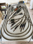
Am learning new things every day!
My isolating rails are all within the points….
Here’s a pic of my temporary setup until loft room is ready in about a month.
-
Walkingthedog

- Posts: 5050
- Joined: Thu Oct 04, 2018 5:51 pm
- Location: HAZLEMERE, BUCKS.
- Contact:
-
Range Rider
- Posts: 41
- Joined: Mon Feb 27, 2023 12:41 pm
- Contact:
Re: Hornby Dublo 3 Rail
Am trying to understand how isolation switches work… are there different colours for different uses? Points, signals, isolation rails & anything else? The isolation switch needs 2 wires to connect to 2 connectors on the controller or just one? Then there are 3 connections on the electric points… would appreciate some guidance on how the linking/connections work.

Re: Hornby Dublo 3 Rail
Isolating switches/levers are just basic On/Off switches. So in one position the circuit is opened and no power flows out of the switch In the other position the internal contact is closed and power flows out to the rails or whatever is to be switched. You only need one rail feed to go into the switch from BEFORE the isolation section and then the other connection goes to the rail of the isolation section. Note if the isolating section is say in a through platform, then normally two isolating sections are needed one at each end of the sections length. The rail in between these two sections is feed from the On/Off switch.
Point Switches/levers for solenoid point motors are Passing Contact or sometimes called Momentary contact. They offer Off-On-Off contact connection, so as when the lever is at each end of its travel there is no power flowing to the solenoid point motor but as the lever travels from one end to the other it momentarily passes an On connection and sends a pulse of power to the motor. There are two On contacts inside the levers casing. One for moving the point motor one way and the other for moving back again. The Point switch has one leg of a power supply (often 16v AC) into its common connection and two connections lead off to the actual motor. The motor has three wires/connection and the third one is the return back to the power supplies other terminal. On no account use a locking On lever or switch for solenoid point motors. The motors must only ever have a short momentary pulse of power to their coils.
The final type of switch or lever encountered is the... On-On type These provide a single input feed that can be switched to either of its two output connections and the selected output is always providing power to whatever is connected to it. There use is usually for two aspect colour light signals or other switching needing always live outputs depending on the levers position.
Much of what you are asking about is shown and described on my electrical pages (first two pages particularly) here https://www.brian-lambert.co.uk/Electrical_Page_1.html
 << Click the Icon to go to my website
-
Range Rider
- Posts: 41
- Joined: Mon Feb 27, 2023 12:41 pm
- Contact:
-
Range Rider
- Posts: 41
- Joined: Mon Feb 27, 2023 12:41 pm
- Contact:
Re: Hornby Dublo 3 Rail
If I have 4/6 switches banked together to operate points/signals… I understand the bank can be connected as one to one output on the controller. I assume you then have multiple (4/6) common wires connected to the other one output on the controller… do I have this right?
Re: Hornby Dublo 3 Rail
If the levers/switches are for Isolating tracks only on a three rail layout, then one controller feed connects to all switches as well as the middle rail on the main layout and the other controllers output connects to the outer rails. The switches/levers other terminal feeds the isolated middle rail that the switch is to isolate.
See example....
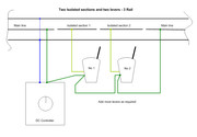
Isolating track switches or levers cannot be used to operate solenoid point motors! These have to have a separate power source, typically 16 volts AC and the switches or levers MUST BE of the passing contact (momentary) style. i.e. Their output is not a permanent one, it is only a brief pulse sent to the motor.
Signals.. Will depend on type? Semaphore solenoid old Hornby Dublo will use the same passing contact as point motors. Colour light signals need a permanent supply and here a On/On switch or lever is used. i.e. one way to feed the red aspect and the other way to feed the green aspect.
See example....
Isolating track switches or levers cannot be used to operate solenoid point motors! These have to have a separate power source, typically 16 volts AC and the switches or levers MUST BE of the passing contact (momentary) style. i.e. Their output is not a permanent one, it is only a brief pulse sent to the motor.
Signals.. Will depend on type? Semaphore solenoid old Hornby Dublo will use the same passing contact as point motors. Colour light signals need a permanent supply and here a On/On switch or lever is used. i.e. one way to feed the red aspect and the other way to feed the green aspect.
<< Click the Icon to go to my websiteWho is online
Users browsing this forum: No registered users and 17 guests