Page 75 of 170
Re: WEST ORTON
Posted: Thu Jun 30, 2022 10:05 am
by RogerB
That's the outfit I used Steve. You're in safe hands. R-
Re: WEST ORTON
Posted: Thu Jun 30, 2022 10:45 am
by teedoubleudee
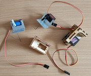
If you don't want to scratch build your own, there are a few different tyes of servo mounts available Steve. Some laser cut ply, some pre-formed alloy some plastic and some 3D printed. Apart from those specifically designed for RC aircraft use many are designed primarily for point changing ie horizontal movement and others can be adapted for vertical movement for semaphore signals. I've used them for all purposes including uncoupling.
A couple from my spares box:

Re: WEST ORTON
Posted: Thu Jun 30, 2022 10:56 am
by Steve M
teedoubleudee wrote: ↑Thu Jun 30, 2022 10:45 am
If you don't want to scratch build your own, there are a few different tyes of servo mounts available Steve. Some laser cut ply, some pre-formed alloy some plastic and some 3D printed. Apart from those specifically designed for RC aircraft use many are designed primarily for point changing ie horizontal movement and others can be adapted for vertical movement for semaphore signals. I've used them for all purposes including uncoupling.
A couple from my spares box:

I ordered a mixed batch from MERG - 3D printed and a mix of single, double and quad mounts - I need every variation going!
In fact I’m fiddling around with the first double servo mount this morning trying to establish a template for mounting them in alignment with the signals above the board. Should make for a repeatable process to fit the others.
Re: WEST ORTON
Posted: Thu Jun 30, 2022 11:04 am
by RogerB
Sorry to say Steve, that they all seem to be a PITA to fit especially when you are upside down. I opted for the laser cut version that you assemble yourself on the basis that there was enough room to place the screws without blue tack. In the end though I found a better method. I used some double sided 3M sticky tape that enabled me to put the operating wire through the board then stand up [ouch] and check alignment prior to sticking them to the board and then getting down again [ouch] to very carefully screw them home. A little easier in my case as the board is only 2' wide so checking vertical alignment in both planes was fairly easy. Good luck. R-
Re: WEST ORTON
Posted: Thu Jun 30, 2022 2:30 pm
by Steve M
Roger, more a pain in the neck from my experience this morning.

I think I have a way of aligning and fitting sorted out though. Nothing connected or tested yet but if it works I will post pictures and an explanation.
If it all goes quiet, you know it didn’t work.

Re: WEST ORTON
Posted: Thu Jun 30, 2022 2:35 pm
by RogerB
It would be just as interesting to know what you tried - even though it didn’t work. R-
Re: WEST ORTON
Posted: Thu Jun 30, 2022 5:41 pm
by Steve M
OK Roger, the story so far.......
When building the signal kit, I drilled out the base of the post and epoxyed a short length of metal tube. I settled on a 2mm inside diameter copper tube into the post then sleeved that with a 3mm brass tube secured with superglue.
I have drilled two holes in the baseboard. One sleeved with a brass tube to accept the 3mm section now attached to the base of the signal, the other sleeved with a plasticard tube to guide the control rods.
Both tubes are cut off flush above and below the baseboard.

I made some mounting plates from 3mm ply and predrilled four holes for mounting screws.

The plate is then screwed under the baseboard,more or less centrally over the two sleeved holes, and the control rod hole drilled through. This provides a guide for mounting the servo and the four corner screws give a positive and repeatable location for the plate.

Demount the plate after marking its orientation with a pen, then using the hole in the centre as a guide, mark the location of and predrill the holes for the servo bracket.

Demount the bracket and open up the central hole - I used a 20mm forstner bit - then fix the bracket with the servos to the plate.

Back to the signal. Mark and cut the mounting tube flush with the underside of the baseboard then tap a thread to suit a short M2 bolt. Mount the signal into the baseboard and secure in place with the bolt and washer. This stops the servos pushing the signal out of the board on the upstroke.

Next is to secure the servos on the bracket and mounting plate in the predrilled holes under the board. They should all line up.

That’s all for today as I’ve been called in for my dinner, but next will be to deal with setting up the servos and fixing the MERG unit in place.
Re: WEST ORTON
Posted: Fri Jul 01, 2022 7:00 am
by RogerB
Brilliant - and much more professional than I would have thought of or could have done. I think success is just around the corner. Thanks. R-
Re: WEST ORTON
Posted: Fri Jul 01, 2022 7:45 am
by teedoubleudee
Steve, get yourself one of these. Invaluable when playing with servos as they can become faulty. Also when you come to install a servo you can set the mid position prior to mounting and setting the linkage length. Cheap as chips from eBay etc.
https://www.amazon.co.uk/AZDelivery-Cur ... s9dHJ1ZQ==
Re: WEST ORTON
Posted: Fri Jul 01, 2022 8:55 am
by RogerB
All the MERG servo control boards have a “set mid point” capability. R-


