Page 1 of 2
Multi pin connector plugs
Posted: Tue Jan 26, 2021 5:07 pm
by tigger449
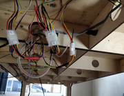
I'm designing a mimic panel for my layout. I'd like to produce a panel that is mounted in its own box and can be disconnected from the layout. I'm looking at multi-pin connector plugs like DIN and Sub D but I'm not sure about how much power these little connectors can handle. What sort of things have other people used?
Re: Multi pin connector plugs
Posted: Tue Jan 26, 2021 5:15 pm
by Steve M
You’ll find the limit will be determined by the size of wire that will fit the soldered end of the pins. Easy to solve though, use two pins for joining bus wires and CDU wires.
I did mine with 27 pins (not easy to solder) and connected them to a tag strip. Much easier to connect to a tag strip under the board.
Re: Multi pin connector plugs
Posted: Tue Jan 26, 2021 7:21 pm
by darkscot
Re: Multi pin connector plugs
Posted: Tue Jan 26, 2021 9:00 pm
by Brian
A lot will depend on the number of connection ways needed.
The last Analogue panel I built for my club had 4 x 25 way Sub D connections. But my own personal layouts panel has just a 4 way and a 2 way aviation plug and socket as I'm using CBus for all operations and indications plus two DCC feeds.
Most Sub D connectors are rated at 3 or 5 Amp per pin. But cheaper ones are not good at being disconnected and reconnected regularly!
Re: Multi pin connector plugs
Posted: Mon Feb 22, 2021 8:00 pm
by Ninemil
Please excuse my ignorance here but I notice that the question is about how much power the little connectors can handle.
Thinking about the cable itself though, if using Sub D connectors, or DIN come to that, do you use an 'off-the-shelf' cable or do those not have enough current carrying capability?
Re: Multi pin connector plugs
Posted: Mon Feb 22, 2021 8:19 pm
by Steve M
Ninemil wrote: ↑Mon Feb 22, 2021 8:00 pm
Please excuse my ignorance here but I notice that the question is about how much power the little connectors can handle.
Thinking about the cable itself though, if using Sub D connectors, or DIN come to that, do you use an 'off-the-shelf' cable or do those not have enough current carrying capability?
The answer is in post #2. For heavier current use more than one pin.
Re: Multi pin connector plugs
Posted: Mon Feb 22, 2021 11:43 pm
by Tricky Dicky
The use of multi pin connectors was discussed recently in this thread.
viewtopic.php?p=30440#p30440
Richard
Re: Multi pin connector plugs
Posted: Tue Feb 23, 2021 9:26 am
by Brian
If using ready made D connector cables as I stated in the post linked to above by TD, you will also find the wires inside (cores) are very fine. So where solenoid point operation is required you will probably have to use 3 or possibly 4 cores all connected together.
Cheap Sub D plugs and sockets will not last long if continually being inserted and pulled apart. More expensive Sub D will be better. Most Sub D connectors are rated at 3 Amp and some are 5 Amp per pin.
Re: Multi pin connector plugs
Posted: Tue Feb 23, 2021 9:48 am
by teedoubleudee
Another option you might want to consider. Cables for use with ATX computer power supply units are made with substantially thicker cables and larger molex pins/sockets to cater for higher current transfer. The only downside is because the pins are slightly loose in the plastic housing they can be tricky to join but once connected they stay connected!
I recently used 4x 4-way 150mm extension cables cut and spliced to join two baseboards.

Bigger versions available like these:
https://www.ebay.co.uk/itm/PSU-Power-Ex ... 1342203572
Re: Multi pin connector plugs
Posted: Tue Feb 23, 2021 4:43 pm
by Brian
If you have a reasonably sized wallet

then the Jones plugs, sockets and covers (covers are called "Hoods") are possibly the Bees Knees of multi pin connectors. They are available in various pin configurations with 20 pin the largest . Example...
https://www.mouser.co.uk/Search/Refine? ... =152770435
I have used them on a club control panel, where plug together and undoing is a regular action and they never fail!
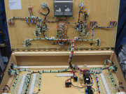
You can just see them in the attached image, two on the left and one on the right with the green and white 16/0.2mm wires attached to their connections ...


