Hi All,
I'm seeking some wiring ideas for my layout.
I have a large shed with basically a 'U' shaped set of tables and about 30 sets of points. Each table can be separated and are linked electrically with RCA Plugs - not a problem. Now I need to bring the extra wires (4 from each) from the point motors (Gaugemaster Seep) to my desk control panel. My idea so far is to connect the cables, like the main power cables, via male/female DiN plugs - that's a lot of plus and a lot of cables.
I'm just looking for any ideas that others have come up with to do the job.
Best Rgds,
Dave R.
Mod... Topic moved to the Wiring and Electrical forum section where it should receive more views.
Wiring issue

Re: Wiring issue
Multipin plugs and sockets will really depend on the number of circuits needed per connection?
25 way D connectors are often used. Wire size up to 16/0.2mm can be soldered to their bucket connections. If you need larger current carrying link two or more pins and mating sockets together. If more than 25 way reverse Male for Female on the other one to prevent accidental wrong connection.
Note; Seep solenoid motors have two operation and one return wire. But the return can be shared by all motors, so each motors return taps onto the main single (Common) return wire for all motors. But I would increase that wires size especially where two or more motors move at once from one switch / lever operation e.g. a cross-over pair of points. If you then need point indications from the Seeps run a positive feed wire out to all the motors and tap off these to each Seeps "F" solder pad then from "D" and "E" pads two smaller sized wires run back to the panel indication LEDs and the supply Negative is also feed to the panel for the LEDs return. What voltage should be used? Normally 12v DC but even 5 volts DC can be used! Don't for get to add a series resistor for each lit LED.
Otherwise perhaps consider looking at using a CBus control system? Two twisted wires supply data and a 12 volt regulated power source feeds everything. MERG sell kits for all types of controls or you can obtain ready made items from suppliers like Megapoints then only a 4 way connection is needed!
I'm using this method with MERG kits on my new layout and I've opted for 4 way Aviation connectors - See further down this page ... Link to web page All operations and indications are over the two wires.
 << Click the Icon to go to my website
Re: Wiring issue
I agree with Brian that with that many points it is seriously worth considering digital control, but it would work out quite expensive.
The problem with 25 way plugs/sockets is you have 50 connections to wire up. What I have done in the past is use a ready wired cable with a plug and socket already fitted. Then I cut the cable in half and then solder each wire to a terminal board. You still have 50 wires to solder (or you can use screw terminals) but it is MUCH easier than soldering wires into the plug/socket. Also if you have a bad connection it is much easier to trace it with the terminals. The only down side is that pre-made cables tend to be expensive, though it would work out cheaper than digital control.
The problem with 25 way plugs/sockets is you have 50 connections to wire up. What I have done in the past is use a ready wired cable with a plug and socket already fitted. Then I cut the cable in half and then solder each wire to a terminal board. You still have 50 wires to solder (or you can use screw terminals) but it is MUCH easier than soldering wires into the plug/socket. Also if you have a bad connection it is much easier to trace it with the terminals. The only down side is that pre-made cables tend to be expensive, though it would work out cheaper than digital control.
Modelling post war LMS. DCC control via Roco z21 & multiMAUS
-
teedoubleudee

- Posts: 1116
- Joined: Fri Oct 05, 2018 2:53 pm
- Location: Downham Market
- Contact:
Re: Wiring issue
That's exactly what I'm doing to connect a pair of boards only I'm using short computer PSU extension cables. I only have 16 connections so 4x 4-way Molex plug/sockets does the trick nicely.darkscot wrote: ↑Sat Jan 30, 2021 10:33 am I agree with Brian that with that many points it is seriously worth considering digital control, but it would work out quite expensive.
The problem with 25 way plugs/sockets is you have 50 connections to wire up. What I have done in the past is use a ready wired cable with a plug and socket already fitted. Then I cut the cable in half and then solder each wire to a terminal board. You still have 50 wires to solder (or you can use screw terminals) but it is MUCH easier than soldering wires into the plug/socket. Also if you have a bad connection it is much easier to trace it with the terminals. The only down side is that pre-made cables tend to be expensive, though it would work out cheaper than digital control.
Most people are shocked when they find out how bad I am as an electrician
Re: Wiring issue
A small word of caution when using ready made D connector cables. Frequently their internal wires are very fine, less than 7/0.2mm and this when needed for larger current requirements such as Solenoid point motors and returns is too small, so you then double or treble up their cores to make an overall larger wire size. But of course in doing so you reduce the number of circuits passing through the cable! 
<< Click the Icon to go to my websiteRe: Wiring issue
Hi All,
Thank you for your feedback, greatly appreciated.
My original small layout was purely DC so moving up to the lowest level of DCC is going to be interesting, to say the least. I have two BUS lines running around my layout, one for track power and one for point, lighting etc., as I said, each table wires joined by RCA plugs. When it comes to bringing the wiring from the point motors to the main board I did think of using those ribbon cables and, after your comments about voltage etc., I'm glad I hadn't made a firm decision on that.
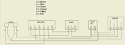
If you'll excuse the sketch, the attached drawing is of the wiring I've done for each point motor and, following tests with a small dummy board, this works just fine. In the mean time I'll certainly be looking at the two links to see waht they offer.
Best Rgds,
Dave R.
Thank you for your feedback, greatly appreciated.
My original small layout was purely DC so moving up to the lowest level of DCC is going to be interesting, to say the least. I have two BUS lines running around my layout, one for track power and one for point, lighting etc., as I said, each table wires joined by RCA plugs. When it comes to bringing the wiring from the point motors to the main board I did think of using those ribbon cables and, after your comments about voltage etc., I'm glad I hadn't made a firm decision on that.
If you'll excuse the sketch, the attached drawing is of the wiring I've done for each point motor and, following tests with a small dummy board, this works just fine. In the mean time I'll certainly be looking at the two links to see waht they offer.
Best Rgds,
Dave R.
Re: Wiring issue
Hi
In your drawing you show a "Power Box", This is shown as feeding both the CDU input and the LEDs.
My question is what is this Power Box? i,e, what is its output type - AC or DC and rating Volts and Amps??
Ideally a CDU needs around 16 volts AC as an input or 19-21 volts DC. But LEDs don't really need that sort of power and a 12 volt regulated DC supply or even 5 volts DC will work LEDs happily. with suitably sized Ohm resistors.
<< Click the Icon to go to my websiteRe: Wiring issue
Hi Brian,
The power box is basically the BUS line that comes from an old DC controller accessories terminals which gives out 16 volt AC. I understand that it's more than adequate for led's, but they pump along quite nicely. I did change some of the original resistors for certain lights, mainly because they appeared far too bright, even from a lower 12 volt DC.
Best Rgds,
Dave R.
Re: Wiring issue
Hi
Whilst LEDs will illuminate on AC power it doesn't do them much good, as in the UK they are blocking the reverse polarity every 50th of a second. Its far, far better to apply a DC power source to them. In your case the simplest would be to remove the two LED feed wires from the power supplies 16v AC terminals and wire to a Bridge Rectifier (or 4 diodes wired into a bridge) Connect the AC side of the bridge to the AC terminals along with the CDU pair of feed wires and then connect the formerly removed two wires to the DC connections on the Bridge ensuring that + Positive goes to the Seeps and then the LED Anodes. Bridge rectifiers cost less than £1 Example... https://www.bitsbox.co.uk/index.php?mai ... cts_id=946
Whilst LEDs will illuminate on AC power it doesn't do them much good, as in the UK they are blocking the reverse polarity every 50th of a second. Its far, far better to apply a DC power source to them. In your case the simplest would be to remove the two LED feed wires from the power supplies 16v AC terminals and wire to a Bridge Rectifier (or 4 diodes wired into a bridge) Connect the AC side of the bridge to the AC terminals along with the CDU pair of feed wires and then connect the formerly removed two wires to the DC connections on the Bridge ensuring that + Positive goes to the Seeps and then the LED Anodes. Bridge rectifiers cost less than £1 Example... https://www.bitsbox.co.uk/index.php?mai ... cts_id=946
<< Click the Icon to go to my websiteRe: Wiring issue
Hi Brian,
Yes, food for thought . I certainly didn't think about the switching that happens on 50Hz supply, just that all the lights come on and look great. It wouldn't be too much of a hassle to fit the bridge.
Best Rgds,
Dave R.
Yes, food for thought
Best Rgds,
Dave R.
Who is online
Users browsing this forum: No registered users and 0 guests