Beechmore
Posted: Tue Feb 07, 2023 4:50 pm
I've just joined the forum, so thought I would give some details of the layout I intend to build.
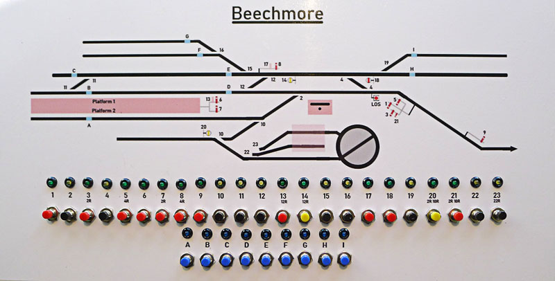
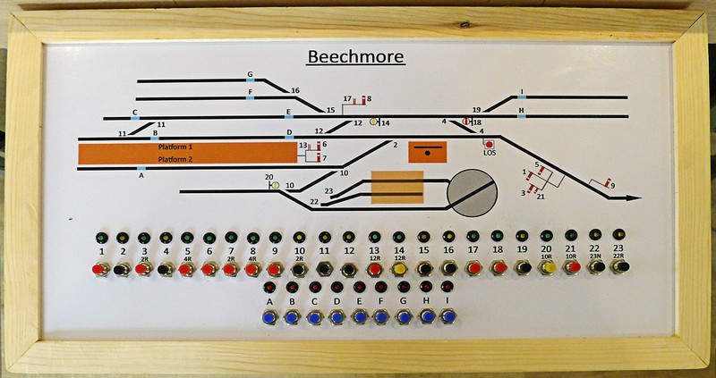
The overall format is a terminal to fiddle yard end to end, built on 4 baseboards, each measuring 4' x 2' 6".
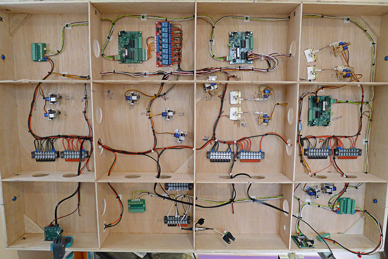
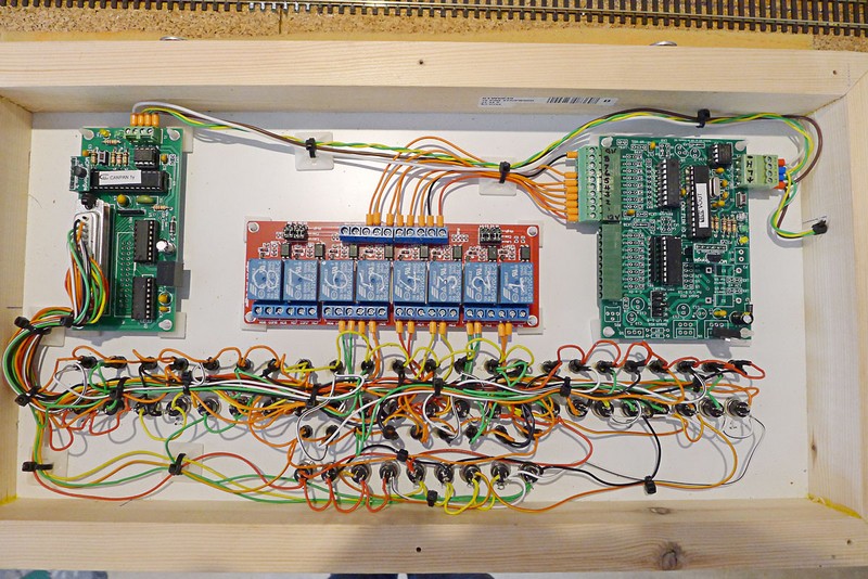
Track is Peco code 100 and all points will be electrofrog, using DCC for control of locomotives. Points will be operated by servos and it is my intention to have working semaphore signals, also operated by servos. These servos will be driven by MERG modules in an effort to keep wiring to a minimum, but having wired a fair bit already, I'm not sure how successful I have been in this respect.
I hope to include some interlocking on the controls, but this will be limited. A previous layout was fully interlocked, but the number of relays under the baseboards to achieve this was enough to rival an old GPO telephone exchange. Interlocking on the new layout will just prevent a signal being cleard if the correct route hasn't been set.
I don't have any photographs of the progress to date, which is virtuallly all of the track laid and associated wiring, but I will take some over the next few days and update this thread when I do.
The overall format is a terminal to fiddle yard end to end, built on 4 baseboards, each measuring 4' x 2' 6".
Track is Peco code 100 and all points will be electrofrog, using DCC for control of locomotives. Points will be operated by servos and it is my intention to have working semaphore signals, also operated by servos. These servos will be driven by MERG modules in an effort to keep wiring to a minimum, but having wired a fair bit already, I'm not sure how successful I have been in this respect.
I hope to include some interlocking on the controls, but this will be limited. A previous layout was fully interlocked, but the number of relays under the baseboards to achieve this was enough to rival an old GPO telephone exchange. Interlocking on the new layout will just prevent a signal being cleard if the correct route hasn't been set.
I don't have any photographs of the progress to date, which is virtuallly all of the track laid and associated wiring, but I will take some over the next few days and update this thread when I do.