Reversing loops -- advice please!
Posted: Sat Mar 04, 2023 4:09 pm
Firstly, hi all. I haven’t been here for a while, busy plugging away at my layout. I hope that everyone is OK.
I wonder if I could pick the collective brains here on the wiring of reversing loops please?
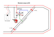
I’ve previously taken a look at both the Peco and Hornby return loop set-up, along with a couple of YouTube videos, and understand the principles. However, having thought about it, I wonder if the following approach would work? It seems simpler to me. BTW, I’m modelling in OO, with DC power.
The Hornby R618 isolating track, unlike the Peco equivalent, has breaks in both rails. My idea was to create a return loop including 2 x R618 sections positioned at sensible points in the loop, connecting a SPDT switch across each of them so that I can make or break both sides of the track feed at the same time. Let’s call them ‘A’ and ‘B’. So, when getting ready to run a loco. via the loop, I first close the switch on ‘A’ (to complete the track circuit), open the switch on ‘B’ (to break the track circuit) set the points accordingly and drive the loco. into the loop, passing over ‘A’ and stopping just before ‘B’. I then break the track circuit at ‘A’, make the track circuit at ‘B’, set the points to the opposite throw, change controller direction and drive out the loco. A bit long winded, but I hope that you get what I’m driving at.
To my feeble, old-aged mind, I can’t see why this won’t work. There’s no risk of cross-connecting track power as I see it, because of the total isolation at either ‘A’ or ‘B’. Will that work, or have I missed the glaringly obvious somewhere?
Hornby’s reverse loop idea uses 2 x R618 in a similar manner but uses an R044 on-on switch to reverse track power.
If my idea is a non-starter, then I’d go for the Hornby version of the reversing loop, but in that case I’d like to replace the R044 switch with something else. However, I’m not sure what that would be or how to wire it.
I can upload diagrams at a later date if that helps (a picture tells a 1000 words and all that).
TIA
Cheers, Clem
