Hi Brian, I have been reading your excellent article on Baseboard Construction, 1st class. Can I just ask what is ‘By using PCB sleepers and gluing and pinning or screwing the PCB to the end of the board you then soldering ‘ etc. What are PCB Sleepers I have not seen this term before? I am just using ordinary HORNBY track at the moment and cant see anything like this on their website. I am sure this is a daft question but will need to tackle this part of my build next. Many thanks
Derek
PCB Sleepers

Re: PCB Sleepers
Hi Derek
You won't find anything like that on the Hornby site. They are sold by specialist suppliers.
Examples (there are others)... https://www.clfinescale.co.uk/online-st ... p136648069
https://www.railroomelectronics.co.uk/C ... Page1.aspx
You won't find anything like that on the Hornby site. They are sold by specialist suppliers.
Examples (there are others)... https://www.clfinescale.co.uk/online-st ... p136648069
https://www.railroomelectronics.co.uk/C ... Page1.aspx
 << Click the Icon to go to my website
Re: PCB Sleepers
Hi Brian well thats an eye opener for me! I can see now what you are describing in your Hints and Tips section (which is fascinating to a newbie btw) and will get ordering straight away! As an aside I had bought Dowels from DCC Concepts but they require a two step drilling process and whilst the product is very well made trying to clear out the second surface hole exactly in the centre of the first one I have found a real trial and almost impossible. I have reverted to your suggestion of bolts which is far better. One again thank you for your help. Regards
Derek
Derek
Re: PCB Sleepers
HI Derek,
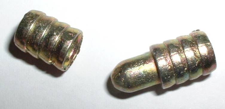
Bolts with ideally a wing nut and washers are fine for pulling two abutting baseboards together tightly, but I would still use some basic alignment aid like cabinet makers dowels. https://www.brian-lambert.co.uk/images/Dowels.jpg
These need just one hole, often either 7mm or 8mm dia. The two boards are connected together and the top surface is ensured to be level across the join, then drill from one side right through to the other side in at least two places. Part the boards and put some woodworking PVA into the holes and tap the dowels in until the bullet end base is flush with the outer face of the baseboard timber and the open dowel is tapped in fully into the opposite boards end framing.
Dowels are sold again by specialists such as these examples... https://www.ebay.co.uk/str/stationroadb ... 3561.l2563
<< Click the Icon to go to my website-
Tricky Dicky
- Posts: 377
- Joined: Fri Oct 05, 2018 6:49 pm
- Contact:
Re: PCB Sleepers
The process for the DCC Concepts dowels is a three step process, are you doing it correctly? Step 1 is to drill a small diam. hole through the ends of both boards whilst they are clamped together, this establishes the centre of the dowel hole. Step 2 is to drill a 19mm counterbore with a flat bit deep enough for the flange of the dowel to sit in flush. Step 3 being to drill the 13mm hole again with a flat bit. The small diam. drill should provide a centre point and initial guide hole for the spike on the 19mm dill to follow, likewise the hole generated by the spike on the 19mm flat bit will act as a centre hole and guide for the final 13mm hole.Del Boy wrote: ↑Mon May 15, 2023 10:36 am As an aside I had bought Dowels from DCC Concepts but they require a two step drilling process and whilst the product is very well made trying to clear out the second surface hole exactly in the centre of the first one I have found a real trial and almost impossible. I have reverted to your suggestion of bolts which is far better. One again thank you for your help. Regards
Derek
Richard
Re: PCB Sleepers
Brian, Richard thank you both for the extra guidance, i will put this to good use when I have time to do a bit more.
Richard I felt sure I followed the DCC instructions (I guess not now) so will have another go but this time following your advice and it does make sense compared to what i was doing, drilling out the hole first and then trying to just trim out the flange. When we get home will try that immediately.
Thanks both once again.
Derek
Re: PCB Sleepers
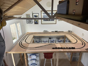
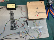
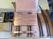
Making some progress at last! I have taken your advice and completely reworked my Baseboards in Ply and I have to say it was much easier to work with than the Fibreboard stuff Hornby and Peco suggest in their literature. Whilst this all looks fairly boring at the moment it's a sort of testbed for the new skills that I am trying to learn. I have put a trap door in on the bottom right of the photo so that I can access the track more easily (old bones and all that) and dreading trying to cut and wire later! I have to say this shot is just the basic layout, yet to lay the cork and tackle the rail cutting and aligning. I have also made a test rig up to see how best to wire my Turnouts, if you want a laugh take a look! I guess the good news is (thanks in no small way to the chaps at Gaugemaster) is it works! Away for a while now but looking forward to building the Mimic Board and fixing some track for real.
Regards
Derek
Regards
Derek

Re: PCB Sleepers
Those hinges need spacing up from the baseboard by AT LEAST the height of the rails, otherwise the track will be damaged when the flap is lifted.
Re: PCB Sleepers
Like this example... https://www.brian-lambert.co.uk/images/ ... idge-2.gif
 << Click the Icon to go to my website
Re: PCB Sleepers
When using PCB sleepers do not forget to groove thru’ the copper between the rails to avoid a short rail to rail.
These are replacement for original useless vero-board ones. The x are for screw holes not polarity.
These are replacement for original useless vero-board ones. The x are for screw holes not polarity.
Who is online
Users browsing this forum: No registered users and 1 guest