Page 1 of 3
Stay alive capacitor- wiring
Posted: Mon Mar 17, 2025 8:26 pm
by Carl L
Not my strong point - electrics.
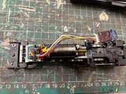
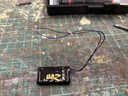
The engine is a Bachmann A2, fitted with a Hattons decoder. Please could some advise where I solder the two wires to fit a DCC Concepts stay alive capacitor. Thank you.


Re: Stay alive capacitor- wiring
Posted: Tue Mar 18, 2025 10:00 am
by Brian
Hi
Guessing now but as the decoder has two wires unused (Green & Purple) I suspect its these two that connect to the Stay Alive boards wires.
However, you will need to determine which of the two decoder wires is the Positive and which of the Stay Alive is the positive. Then and only then, join them by in line soldered joints and cover the bare soldered joints with ideally Heat shrink tubing or use a quality insulating tape. Reference to the two items manuals should tell you which is the Positive on each.
Re: Stay alive capacitor- wiring
Posted: Tue Mar 18, 2025 11:21 am
by Steve M
Checking on an entry on the old Hattons site shows a picture of that decoder alongside a stayalive that leads me to think Brian's assumptions are correct.
The stay alive wires should be black - negative, blue - positive. On the decoder itself, I would remove the heat shrink and trace the two spare wires back to where they are soldered.
One will likelybe connected to the bridge rectifier (negative) and the other to a positive solder pad. The bridge rectifier will probably look like four SMD diodes in a close arrangement on the decoder.
That should help identify which way round to join the wires.
Of course it may just release the magic smoke contained in all decoders,

Re: Stay alive capacitor- wiring
Posted: Wed Mar 19, 2025 6:26 pm
by Carl L
Appreciate the replies, thank you.
Wish me luck

Re: Stay alive capacitor- wiring
Posted: Wed Mar 19, 2025 8:03 pm
by Steve M
Bear in mind that the magic smoke is what makes electricity work. Once released you can't put it back in the wires.

Re: Stay alive capacitor- wiring
Posted: Wed Mar 19, 2025 9:14 pm
by Carl L
Well I have to say I bottled it

I took the shrink wrap off and where the two wires are soldered to are just so, so small, I put it back together again.
I’ll leave it for another day when I’m feeling brave

Re: Stay alive capacitor- wiring
Posted: Wed Mar 19, 2025 9:48 pm
by Steve M
Could you put a picture of the 'naked' decoder on here? Might help identify which wire is which. Also once identified just join the wires rather than trying to solder to the decoder itself.
Re: Stay alive capacitor- wiring
Posted: Thu Mar 20, 2025 12:11 pm
by Brian
An easier method of checking might be to plug the decoder into a loco sitting on DCC powered rails and with a multimeter switched to its DC voltage range of 20v or greater and see which of the two wires is the Positive.

Re: Stay alive capacitor- wiring
Posted: Thu Mar 20, 2025 3:26 pm
by Steve M
Agreed Brian, but you must remember that as far as I am concerned all electrical stuff is witchcraft to me.
Re: Stay alive capacitor- wiring
Posted: Thu Mar 20, 2025 4:03 pm
by Brian
Off to polish my Broomstick now
