Auto Signal Control: IR LED transmitter / Receiver Problems

paul1066
Posts: 37
Joined: Wed Jan 02, 2019 3:17 pm
Contact:

Auto Signal Control: IR LED transmitter / Receiver Problems

#1

Post by paul1066 »

Hi all, happy new year, so come the new year, I decided to get on with a project I've long been putting off as I'm not much of a electronics wizz, I've started building some automatic signal controls by following the excellent tutorial by Everard Junction (link below - go to 11:40 to see the actual transmitter / receiver). All seems to be OK with the exception that I can't get the train detector to work. EJ's tutorial uses an IR LED transmitter and IR LED receiver - the circuit diagram is below. Basically waving some tin foil over the IR transmitter and receiver, I can't get the colour light sequence to follow EJ's example, even if I point the transmitter LED directly at the receiver end to end. Now I know it actually works as I connected a spare LED transmitter to a 3V button cell and pointed that at the receiver and the colour light sequence activated as it should do. I've tried changing the transmitter LED to make sure it wasn't duff and still no joy. I'm guessing the LED transmitter in the circuit is "underpowered?" as I can activate the sequence with the LED attached to a button cell. So my next move is to buy different LED transmitters and receivers and see if that works. Before I do that, is there anything else I should try?

Many thanks

Paul

Image

https://www.youtube.com/watch?v=wL4I3MXxKZo&t=1019s
User avatar
Brian
Posts: 2171
Joined: Thu Oct 04, 2018 3:49 pm
Location: SE Kent
Contact:

Re: Auto Signal Control: IR LED transmitter / Receiver Problems

#2

Post by Brian »

Hi
Several things may be the cause.... But two to check are
Incorrectly wired LED IR Tx Is it reversed?
PIC not fully programmed.

Use your mobile phone camera to see if the TX IR LED is lit. It shows up pink on a camera!
If it is lit then check you programming of the PIC

What IR LED is being used? I like the RPR220.
Image << Click the Icon to go to my website
paul1066
Posts: 37
Joined: Wed Jan 02, 2019 3:17 pm
Contact:

Re: Auto Signal Control: IR LED transmitter / Receiver Problems

#3

Post by paul1066 »

Thanks Brian, I did try the model phone camera trick and the IR Transmitter is illuminated but seemed very "dim" compared to the one I wired to a 3V button cell. Think I'll try different IR transmitters and receivers, the receivers I have are black so I don't know if that affects it as the ones in EJ's tutorial are clear.

Best wishes

Paul
Chris
Posts: 133
Joined: Thu Oct 18, 2018 6:24 pm
Contact:

Re: Auto Signal Control: IR LED transmitter / Receiver Problems

#4

Post by Chris »

Do you have the details of the LED IR as you could always look to changing the resistor in the circuit a quick look on google suggested voltage of about 1.5V but the current is noticeably higher than that of normal LED's at around 50mA
paul1066
Posts: 37
Joined: Wed Jan 02, 2019 3:17 pm
Contact:

Re: Auto Signal Control: IR LED transmitter / Receiver Problems

#5

Post by paul1066 »

Thanks Chris, I bought the LEDs so long ago I don't have the original data so I've ordered some more (the ones recommended by Brian that look easier to install) so I'll try them.

Thanks

Paul
Tricky Dicky
Posts: 376
Joined: Fri Oct 05, 2018 6:49 pm
Contact:

Re: Auto Signal Control: IR LED transmitter / Receiver Problems

#6

Post by Tricky Dicky »

Try using a non-reflective material as a IR barrier. IR can reflect off many surfaces you can often change channels on a TV by pointing the remote at a wall behind you if it is light enough. Your bit of tin foil might be reflecting IR all round and causing the sequence to re-start. I would suggest it is a programming issue, without seeing the program it is hard to advise, I have done some programming of PICAXE but it is not my forte. I advise you to pose your problems on the PICAXE forum, submit both your circuit and program, there are some great minds there and will probably sort you out in no time.

Richard
User avatar
teedoubleudee
Posts: 1116
Joined: Fri Oct 05, 2018 2:53 pm
Location: Downham Market
Contact:

Re: Auto Signal Control: IR LED transmitter / Receiver Problems

#7

Post by teedoubleudee »

My experience of experimenting using IR Tx/Rx detectors and Picaxe chips brings me to the same conclusions as above and echoed by EJ on the video.

If, as you say, the IR components work outside of the program then that proves they are working and correctly wired up regarding polarity.

Have you checked and double checked the correctness of the strip board construction, eg no dry joints, no tiny solder or wire bridges across tracks that shouldn't be there and desired breaks in the copper strips really are broken! It's worth spending 10-15 minutes checking with a meter on resistance setting and audible bleep if you have it. Be sure to remove the power and the Picaxe chip BEFORE doing this exercise as it's presence may give spurious results.

Personally, I would suspect the software program as the main culprit. I am not familiar with the block diagram method of programming these chips as I prefer to write the code directly. The software I use has a "test" function where you can step through each line of code and check the resulting reaction. This is depicted by a picture of the chip showing the pin outputs changing. If you can run a diagnostic on your program before you copy it to the chip I urge to do so, even experience amateur programmers like myself rarely get it right first time! Sometimes the act of copying the software to the chip can fail - use a verify option if there is one.

After you have put it all back together test the circuit and program by forcing each input in turn and check the result.

Lastly, regarding the final positioning of the sensors in the track and the reflective strip. Ambient room lighting DOES affect how these sensors work so try testing with the lights off or dimmed. Rather than using foil I found that a matt white strip to be more consistently effective eg paint of white insulating tape.

Like a lot of this type of project patience and diligence is of the essence. Good luck.
Most people are shocked when they find out how bad I am as an electrician
User avatar
Brian
Posts: 2171
Joined: Thu Oct 04, 2018 3:49 pm
Location: SE Kent
Contact:

Re: Auto Signal Control: IR LED transmitter / Receiver Problems

#8

Post by Brian »

Hi
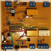
I have several PIC three aspect signal controllers all working very satisfactory. I use a SMPS 12 volt power source to feed all the circuits and each board has a 7805 5v regulator to set the volts for the PICs and to feed the signals (Eckons).
I have some that include a Junction Indicator circuit via the point ahead position (Solenoid motors with twin coil latching relays).
I use both 18M2 and 8M2 PICs

I have found that the IR Rx are always susceptible to ambient lighting of the room. Some lights cause far worse false triggering than others do! Hence fit pots to allow adjustments fordiffering lighting levels where the circuits are used on portable exhibition layouts.
Try placing a small tube around the Tx and Rx IR LEDs to screen them from room lighting to see if the circuit works then.

I'm happy to send you the files and circuits if you use the PICAXE editor 6.1 software. Though they are all for three aspect signalling control.
Image
Image

However, all this said, I have to say that the MERG dual channel Hector IR kit item 72A is absolutely excellent in detection. Currently £9.11 to members. I also have a BlockSignalling Aspect Controller ASP1-NS excellent too.
Image << Click the Icon to go to my website
Tricky Dicky
Posts: 376
Joined: Fri Oct 05, 2018 6:49 pm
Contact:

Re: Auto Signal Control: IR LED transmitter / Receiver Problems

#9

Post by Tricky Dicky »

OK, slightly misread what you were trying to do, I thought you were triggering the circuit by a break the beam type of sensor rather than reflecting IR on the IR Rx. Having watched the video I would not have constructed the sensor circuit as EJ has done but would have rather I would have mounted all the components on strip board.

As TWD said try to eliminate possible circuit errors by testing thoroughly even though when using an IR LED and button cell makes the circuit and program work. You stated that the IR LED in the sensor seemed to emit a poor IR. The thought comes to mind have you confused the 4K7 load resistor in the Rx part of the circuit and the current limiting 220R resistor which would maybe the reason why you think the IR is poor.

If you are using the Logicator flow chart software used by EJ then you can test the program in the software slowing it right down so you can see the effects on the outputs as the program runs and responds to inputs. Mistakes to look out for in the programming are getting the YES/NO in the decision cells the wrong way round also take care with drawing the loops, one arrow the wrong way round and it will not work.

Coming back to the circuit as Brian has said try to shield the Rx from spurious IR by enclosing it in a tube. You can get a combined IR Tx and Rx sensor which I have found more stable.

Richard
User avatar
teedoubleudee
Posts: 1116
Joined: Fri Oct 05, 2018 2:53 pm
Location: Downham Market
Contact:

Re: Auto Signal Control: IR LED transmitter / Receiver Problems

#10

Post by teedoubleudee »

Tricky Dicky wrote: Thu Jan 03, 2019 11:15 pm .................................................. You can get a combined IR Tx and Rx sensor which I have found more stable.

Richard
In my gas plant project I use a TCRT5000 combined Tx/Rx which is triggered by a small painted white patch on the side of a wagon. It has proved 100% reliable.

You can see it in action in my youtube video of the gas plant project at https://www.youtube.com/watch?v=uwHyUlPsQPY

Skip to 12.46 for a still of the mounted IR Tx/Rx and wagon.
Most people are shocked when they find out how bad I am as an electrician
Post Reply

Who is online

Users browsing this forum: No registered users and 0 guests