So I have three personal rules for adding lighting to my model buildings:
1. If the building has multiple floors I always divide them for a more natural look
2. I like to include an ambient light sensitive circuit so they come on slowly with the dark
3. I HATE light bleed through walls and gaps in badly fitted parts (I think I might have mentioned that before!).
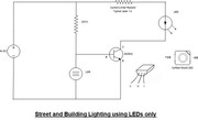
In this example the light sensitive components can be ommitted and just use the LED and a 1k resistor to protect the LED from excessive current.
The light bleed rule proved to be a right pig on this project as the building (from Faller) was made out of paper thin plastic and two coats of paint on the inside of the walls and two on the outside failed to stop it. So in the end I had to cut and fit small pieces of thick card around the windows and doors which finally fixed it.
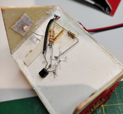
I completely dissasembled the kit down to it's original parts as although the original owner had used tons of glue, much of it was doing nothing! So I rebuilt it, painting the various parts along the way. The electronics were installed into a false ceiling after the four walls had been rebuilt and newly painted doors/windows installed. The false floor was chosen for three reasons. One, it saved me worrying about light bleeding into the roof space and two, the light dependent resistor (LDR) has to be installed where it is unaffected by the light it controls otherwise it just keeps switching itself off again. Reason three it gave me a platform to mount the components.
So the photos below show:
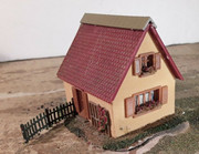
0. The original model as received
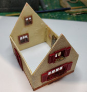
1. The rebuilt cottage shell prior to installing the ceiling
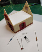
2. The ceiling in place (not stuck down yet) and the required electronic components ready to install.
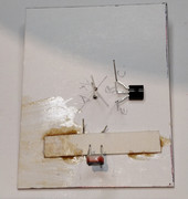
3. The LDR has been installed so that it points out of one of the attic windows. The LED and transistor installed and "legs" labelled to assist me when soldering the circuit together.
4. All components connected together and to the 12v DC supply cable through Hole in ceiling which is now stuck down with model plaster.
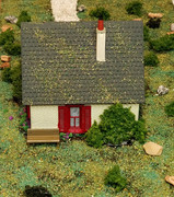
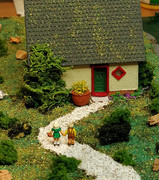
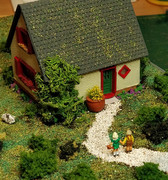
The last three photos show the completed scene before installing in (yet to plant forest!) I tried to take a photo with the room lights out but my phone camera is not up to decent low light shots, so you will have to take my word for it that it does work as intended and NO light bleed.
Finally I have added a picture of the circuit diagram (not my design but widely shared on internet). Note that the LED and 1K resistor can be replaced with the coil of a low current 12v miniature relay to switch several lights or to power filament bulbs (Do not try to drive filament bulbs directly with this circuit as the transistor may be damaged by the current drain). Thanks for looking.
