Having issues wiring lights to decoder
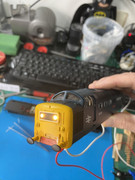
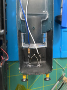
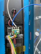
Hi, I need some help please. I have a little project with this Hornby Class 50. I’m adding some lights. That lights are 3.2v , 2 in a sequence and using an online calculator I am using a 390 ohm resistor . Please see images. This is a Hornby TTS sound decoder, and I have done all the correct soldering places. When is used just a standard 12v power supply , the lights work fine. I have tested the cables right back to the decoder socket ( and when the decoder is also plugged in) with a voltmeter continuity test. All seems fine. Just when I put on the track, the lights don’t come on when I do function 0. Tested with a Hornby select and a Gaugemaster prodigy. Any idea where I could be going wrong? Thanks
-
- Posts: 387
- Joined: Fri Oct 05, 2018 6:49 pm
- Contact:
Re: Having issues wiring lights to decoder
If as you say the LEDs emit light when connected to a power supply then that eliminates the possibility that one of them is wired in the wrong polarity. Have you tried the obvious of swapping the two leads (blue & white). One of the confusing descriptions on decoders is what are called outputs. On most decoders there is one output which may be called Common which is in fact a 12V output all accessories such as lights should have their anodes (+) wired to it and all their cathodes (-) wired to their respective outputs which actually sink current rather than source it. When you activate a function internally all the decoder does is connect the respective cathode to the zero volt rail to complete the circuit. This method allows the decoder to sink far greater current then it could source.
Richard
Richard
-
- Posts: 387
- Joined: Fri Oct 05, 2018 6:49 pm
- Contact:
Re: Having issues wiring lights to decoder
Addendum:
On most decoders that have a wiring harness it is the blue wire that is the +12V certainly on all the ones I have had experience with. It is difficult to see which wire on your LEDs is wired to the anode and the cathode but I suggest a simple swap it does not matter which side the resistor is wired to.
Richard
Re: Having issues wiring lights to decoder
Don't forget the white wire output is for forward running, have you tried reversing direction to see if lights work then?
Sorry I'm late but I couldn't get my flip-flops to work
Re: Having issues wiring lights to decoder
I may have completely misunderstood what is in the photo but it looks like you have soldered the two longer (anode) wires of the leds together and then connected both blue and white to the shorter cathode wires. I that's the case then that would explain why it doesn't work but neither would it work on a direct 12v dc power supply.
You need the leds wired in series with the short, cathode, wire at one end connecting to the white wire and the longer, anode, wire connecting to the blue wire. It doesn't matter which side the resistor is on. However, I think I'd have used a 470 ohm resistor to be safe but you may be ok with the 390 ohm one and you can always change it if the leds are too bright.
Re: Having issues wiring lights to decoder
Thanks for all the replies, and yes the one thing I hadnt done was to swap the cables (white and blue) so done that, and it came to life. School boy error. I was worried about blowing the bulbs.Was confused as I thought the Common return they called it was negative so had it on the wrong anode. So to answer another question, on the first LED I had soldered the shorter Anode to the longer anode of the 2nd LED, I did do all the research before i started, but all seems well now, and comes on in the right direction as well. Only small issue I have though, is one side, even though swtiched to the other direction, the bulb looks still on a bit, but very dim.
Richard
Richard
Re: Having issues wiring lights to decoder
Electronics tend to switch the negative (0 volts) supply wire, so on a decoder Blue is always a positive unswitched feed for all functions, therefore White , Yellow, Green and Purple etc wires are all switched negatives.
LEDs when in Series connect LED1 short lead to LED2 long lead. Then decoder Blue wire goes to LED1 long lead and decoder White wire to LED2 short lead. Also the reverse can also be used, so then LED1 long lead connects to LED2 short lead. The Blue wire connecting to LED2 long lead and the White wire to LED1 short lead.
The resistor can go in either the Blue or the White wire. It doesn't matter which. The Ohm rating of the resistor will depend on the final brightness of the LEDs, the higher the Ohm rating the dimmer the LEDs will become. Minimum resistor value for a pair of series white LEDs each with a specification forward LED voltage of 3.5v and an operating current of say 10milliamps, the decoders nominal function output of 12 volts then use 560R or a higher value resistor e.g. 1K or 2K2 or even a greater ohm value as required. 1/4watt (0.25w) will be fine.
Re: Having issues wiring lights to decoder
For dcc use you need to wire your leds as common anode. This means if you are using 3-legged bi-colour leds (2 colours in one 'bulb') the middle leg must be the anode, leaving the outer legs to switch the colours. You can get 3-legged leds which are common cathode and no use for dcc lights.
- bulleidboy
- Posts: 2309
- Joined: Thu Oct 04, 2018 6:30 pm
- Location: Basingstoke, Hants
- Contact:
Who is online
Users browsing this forum: No registered users and 0 guests