Reverse Polarity Switching
Re: Reverse Polarity Switching
Absolutely, and as my eyes get worse my layout gets better haha! One of the solid facts about any creative endeavour, you might mull over little bodges and mistakes but no one else notices them, well mostly...
Re: Reverse Polarity Switching
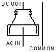
Could you power the signals with ac and then use the seep switch to change the polarity by using diodes.


-
Tricky Dicky
- Posts: 412
- Joined: Fri Oct 05, 2018 6:49 pm
- Contact:
Re: Reverse Polarity Switching
Er! No I think you have a slight misunderstanding of AC, a true AC supply does not have a positive and negative both terminals alternate according to a sine wave. The explanation is quite lengthy so you might want to read this;
https://en.m.wikipedia.org/wiki/Three-p ... tric_power
Which explains how UK domestic power supplies achieve a Live & Neutral or to correctly put it a Phase & Neutral.
Richard
Re: Reverse Polarity Switching
Think about the circuit Richard, The ac in is rectified by the single diode and that give on;y half the sine wave out according to which way the diode is facing. I have used this circuit to reverse dc motors on some of my projects so I know for a fact that it works. Both the wires are from the ac source but the left hand one terminates on the central terminal of a single pole double throw switch (rectangle in drawing), the two diodes are connected to the outer poles in reverse direction, The ac in is then rectified to a half sine wave, depending on the throw of the switch (either positive or negative)
-
Tricky Dicky
- Posts: 412
- Joined: Fri Oct 05, 2018 6:49 pm
- Contact:
Re: Reverse Polarity Switching
Apologies BNB you are absolutely right this is a classic case on my part of getting an idea rolling at the back of my head and managing to get 2+2=5 or should that be 3.  After your first post mentioning 2 diodes the classic full wave rectifier with a centre tapped common came to mind and I could see how that could work exploiting the half waves. I did not give it much further thought as the OP had not mentioned an AC supply and assumed it was DC of which the previous solutions would work. I think your terminology threw me when you mentioned COMMON in the AC supply having only been used to using that term to describe a centre tap on a transformer when talking about AC. You are not wrong as once rectified from the DC perspective it could be termed the COM which is often used to describe 0V or (-)
As for the Wikipedia reference I was wondering if like some people who do not understand how their domestic AC supply works equate neutral with (-) and live with (+) on a battery because you do not get a shock when you touch neutral and say (-) on a car battery where you will get a zap from the positive terminal especially if touching another part of the car.
So folks ignore post#13 (Ah! That is where the problem is) unless you want a greater understanding of your domestic electricity supply.
Apologies for misleading
Richard
As for the Wikipedia reference I was wondering if like some people who do not understand how their domestic AC supply works equate neutral with (-) and live with (+) on a battery because you do not get a shock when you touch neutral and say (-) on a car battery where you will get a zap from the positive terminal especially if touching another part of the car.
So folks ignore post#13 (Ah! That is where the problem is)
Apologies for misleading
Richard
Re: Reverse Polarity Switching
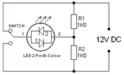
There is a way of doing it with dc too, using a potential divider. A bit inefficient because the resistors are drawing current all the time.


Who is online
Users browsing this forum: No registered users and 13 guests