Point motor switches
Point motor switches
Hello
I am planning to wire up the points on our layout with point motors. The points will be controlled from a mimic panel and I'm trying to make it as user friendly as possible for my two sons.
My plan was to place a switch on the control panel at each point location and I was hoping to have toggle switch that would indicate the set of the points. However, it seems that the spring loaded centre off type of toggle switch is the only one that is suitable for points. The downside of this is that switch does not indicate how the points are set.
Is there relatively cheap type of switch that will do this? Ideally it would be cylindrical to allow drill-hole fitting. I am aware of the hornby and peco lever switches but these are pricey, are too big to place at each point on the mimic panel and require rectangular cut outs.
Hope I'm not asking for the impossible.
Thanks
Re: Point motor switches
Hi,
When using Solenoid point motors (Peco, Hornby, Seep, Gaugemaster etc) then you must ensure the power to the motors coil is only available momentarily and for less than roughly 0.5 Seconds in total.
How do you provide this pulse? Normally by using - Passing contact levers, (On)-Off-(On) sprung to centre off toggle switches, 2 x Push to make non locking push button switches or good old fashioned Stud & Probe.
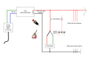
If the switches operation lever has to indicate the point position then you can use On-On toggle switches and a single press to make Push button per point operation. So as no power flows to the toggle switch regardless of its position until the adjacent PB is depressed. Thereby sending the power to the switch and the switch sending the power to the appropriate motors coil. The down side is that two switches (1 x momentary press to make PB and 1 x SPDT toggle switch) are needed per point or pair of points when used as a cross-over pair. Not ideal!
I would always add a Capacitor Discharge Unit (CDU) between the power supply and the first switch. The CDU does two jobs.. A) It provides a beefy pulse of power to the motors coil to ensure it operates well. and B) Once its discharged in milliseconds it cannot recharge again until all operating switches are restored to their Off position, thereby preventing accidental coil burn out due to power remaining On for too long. Normally only one CDU is needed for the whole layout.
Use at least 16/0.2mm equipment wire (0.5mm2) for all solenoid motor wiring.
If you haven't purchased the solenoids seriously consider obtaining motor driven stall point motors such as DCC Concepts iP Analogue or Tortoise which then use standard DPDT toggle switches or if an AC rectified supply SPDT switches.
Much of what you're asking is covered here... Link to items
Re: Point motor switches
Hi - I used 10mm Circular On-On switches ( bought from E-switch on EBay) to control the points on my layout which uses DCC Concepts Cobalt IP Analogue slow action point motors...... using the inbuilt switch on the motor I was able to wire up LED’s to show the point direction, although the writing on the panel surface adjacent to the switch also serves this purpose....... see attached picture
Hope this helps......
Hope this helps......
Re: Point motor switches
Thanks for the prompt replies.
Brian the two switch solution might be a goer. Do you have a wiring diagram for this? I'm a very much a beginner when it comes to electrics.
Hound Dog thanks for your suggestion but the Cobalts are beyond my budget.
Brian the two switch solution might be a goer. Do you have a wiring diagram for this? I'm a very much a beginner when it comes to electrics.
Hound Dog thanks for your suggestion but the Cobalts are beyond my budget.
Re: Point motor switches
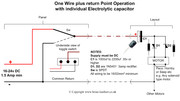
I use the one-wire circuit and CDU for each solenoid and this uses a standard toggle on-on like a SPDT and I have asked about getting the circuit & text so I can post it here. It was removed from a well known website when the site got updated.
The toggle indicates which way the turnout is set.
The toggle indicates which way the turnout is set.
Ron
NCE DCC, 00 scale, very loosely based on GWR
NCE DCC, 00 scale, very loosely based on GWR
- teedoubleudee
- Posts: 1116
- Joined: Fri Oct 05, 2018 2:53 pm
- Location: Downham Market
- Contact:
Re: Point motor switches
Although the circuit provided by Brian above will work fine it doesn't provide a concrete indication that the point blades actually moved. This was, as I understand, a requirement in the OPs opening post. Only some form of physical switch attached to the point blades can provide this in the form of an illuminated bulb or led.
Most people are shocked when they find out how bad I am as an electrician
Re: Point motor switches
Is this page any help? http://www.newrailwaymodellers.co.uk/el ... itches.htmRon S wrote: ↑Mon Feb 11, 2019 9:23 am I use the one-wire circuit and CDU for each solenoid and this uses a standard toggle on-on like a SPDT and I have asked about getting the circuit & text so I can post it here. It was removed from a well known website when the site got updated.
The toggle indicates which way the turnout is set.
Re: Point motor switches
Thanks again Brian
I looked at your LED/Seep solution on Electrical 3 of your website which is also a possibility but it seems to involve a lot more wires running to each motor.
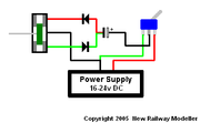
I came across this solution on another forum which I think involves less wiring but is a bit more sophisticated. Do you think it would work?
This is the text that goes with the attached diagram.
When the switch is thrown, the current flows through the point motor until the capacitor is fully charged and then it stops. When you then through the switch in the opposite direction the capacitor discharges through the other side of the point motor making it move in the opposite direction from before until the capacitor is fully discharged. Both times the switch is thrown the point motor only gets a very small burst of power.
Basically it works like Hornby and Peco point switches except it requires DC to work. You should not require a Capacitor Discharge Unit as the capacitor does this job.

Who is online
Users browsing this forum: Google [Bot] and 7 guests


