
That's why I use RPR220 Tx & Rx combined IR LEDs. All in one package and its also easy to fit them between OO sleepers too!
Get mine from eBay sellers in China at around £0.19 each when 10 or more are purchased. Takes about two to three weeks for them to arrive and I've not been let down so far!
Auto Signal Control: IR LED transmitter / Receiver Problems
Re: Auto Signal Control: IR LED transmitter / Receiver Problems
 << Click the Icon to go to my website
Re: Auto Signal Control: IR LED transmitter / Receiver Problems
In the video he does say that the prototyping board is being used for that purpose and that he will solder together the finished working design
The Picaxe software does allow simulation so you can step through switching the inputs etc and see what outputs are responding but as you say that it worked ok with a battery powered IR LED then I doubt its the program at issue.
as your using a transisitor as the switch (IR Rx) the more IR it see's the more it turns on and pulls the 5V from the pin down to 0V program sees this as pin going low and then switches outputs. you can measure the voltage with a meter to see what effect your light is having. ideally low should be 0V and high 5V however below shows the values from the manual that the chips will default switch at given a 5V supply.
TTL (Supply voltage > 4.5V)
Status 'high' if > 2.0V
Status 'low' if < 0.8V
Eg, with a 5V supply: high > 2.0V, low < 0.8V
so if your not turning on the transistor enough with the IR then the voltage isnt going low enough
one easy way to work around this is to use an analogue decision, this is then based on 0-5V and you pick the value that your sensor is achieving it also means that you cna use a reference sesnor to remove the effect of ambient light
The block diagram programming is good for the simple yes no decision but if the program is getting more complex with multiple steps it can be worth making the effort to use the 'Basic' programming as while the text and syntax requires a little more work it actually then reads in plain english what is happening and that can make life easier at a later stage.
anyway hope your new LED's solve the problem and at least you will have the spec of them to know what they will tolerate in the circuit
-
teedoubleudee

- Posts: 1116
- Joined: Fri Oct 05, 2018 2:53 pm
- Location: Downham Market
- Contact:
Re: Auto Signal Control: IR LED transmitter / Receiver Problems
It also allows you to write plenty of comments to help you later (and others) to understand what is going on.Chris wrote: ↑Fri Jan 04, 2019 12:32 pm ..............................The block diagram programming is good for the simple yes no decision but if the program is getting more complex with multiple steps it can be worth making the effort to use the 'Basic' programming as while the text and syntax requires a little more work it actually then reads in plain english what is happening and that can make life easier at a later stage.............................
Most people are shocked when they find out how bad I am as an electrician
Re: Auto Signal Control: IR LED transmitter / Receiver Problems
you can do that in block diagrams too, the best habit is to change the names of pins etc to something that is relevant.
-
teedoubleudee
- Posts: 1116
- Joined: Fri Oct 05, 2018 2:53 pm
- Location: Downham Market
- Contact:
Re: Auto Signal Control: IR LED transmitter / Receiver Problems
Maybe, but I'll stick to my preferred way. Horses for courses 
Most people are shocked when they find out how bad I am as an electrician
Re: Auto Signal Control: IR LED transmitter / Receiver Problems
I prefer writing in basic as there are a lot more complex codes that make more sense and as the manual gives them in detail in basic rather than blocks it does make it easier to develop.
I do at some point intend to utilise my picaxe back into the railway although it may just be for a funicular or something.
I do at some point intend to utilise my picaxe back into the railway although it may just be for a funicular or something.
Re: Auto Signal Control: IR LED transmitter / Receiver Problems
Thanks everyone for the feedback, I need to take all the comments on-board so will get back with an update in a couple of weeks due to work commitments. So far I have built two boards and third breadboard mock-up and all suffer the same problem that the IR part of the circuit does not work as intended, but does work if I shine another IR transmitter directly into the receiver (I've powered the IR transmitter with a 3V button cell) so I guess that shows the circuit / programme is correct. This approach might be a bit old hat, but I don't really want to give up on it as I've spent quite a bit on the picaxe programmer and chips etc so hopefully I can figure out where the problem is.
Cheers
Paul
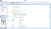
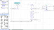
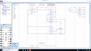
ps this is my programme flow chart
Cheers
Paul
ps this is my programme flow chart
Re: Auto Signal Control: IR LED transmitter / Receiver Problems
I'm wondering is you have C2 correct?
Mine works fine, though I have more checks made between aspect steps to ensure all is still as per the start.
Note this circuit operates a signal with a Junction Indicator (Feather) fitted when a point ahead of the signal is set to cross over direction. Hence the "Is CO High" question in the sequence, as the main aspect has to remain at a single Yellow when the J/I is lit.
Also not shown is that half the PIC operates a second signal!
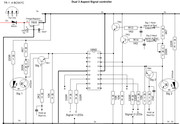
Wiring drawing!
Mine works fine, though I have more checks made between aspect steps to ensure all is still as per the start.
Note this circuit operates a signal with a Junction Indicator (Feather) fitted when a point ahead of the signal is set to cross over direction. Hence the "Is CO High" question in the sequence, as the main aspect has to remain at a single Yellow when the J/I is lit.
Also not shown is that half the PIC operates a second signal!
Wiring drawing!
<< Click the Icon to go to my websiteRe: Auto Signal Control: IR LED transmitter / Receiver Problems
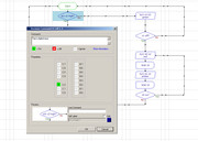
Can you post a photo of the board you have built both front and rear. This may help, also on your flow chart double click on the "is c2 high box" and post the photo of the values shown.
Re: Auto Signal Control: IR LED transmitter / Receiver Problems
Hi all,
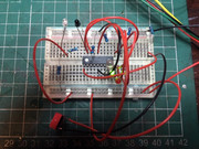
OK I've uploaded a short vid to show how the system works at the mo - I've recreated the board on my breadboard to rule out any of my dodgy soldering - the video is here:
https://youtu.be/FIg56oPHHuM
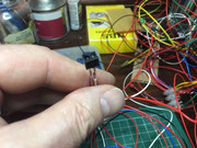
I've uploaded some photos of the breadboard layout and the C2 high box. I've also tried the enclosed IR transmitter / detector as shown in the photo as an alternative to the first two and am having the same problem with detection.
Regards
Paul
OK I've uploaded a short vid to show how the system works at the mo - I've recreated the board on my breadboard to rule out any of my dodgy soldering - the video is here:
https://youtu.be/FIg56oPHHuM
I've uploaded some photos of the breadboard layout and the C2 high box. I've also tried the enclosed IR transmitter / detector as shown in the photo as an alternative to the first two and am having the same problem with detection.
Regards
Paul
Who is online
Users browsing this forum: No registered users and 1 guest