dpdt switches
dpdt switches
The point motors im fitting on the latest layout have a contact on the slide bar that breaks the current to the energised coil once the slide has moved across, so a on-off-on DPDT switch should be ok i think.
Re: dpdt switches
Solenoids? Single Pole Double Throw On-On would do as you say they have a built in cut off switch. You can of course use Double Pole version too but only use one side contacts on the switch.
Motorised? Then Double Pole Double Throw On-On would be fine.
Edit DPDT for solenoid comment added
Motorised? Then Double Pole Double Throw On-On would be fine.
Edit DPDT for solenoid comment added
Re: dpdt switches
All wired up and working, now i would like some Leds red and green on the mimic board to aid the kids, could some kind sole add a simple diagram for this please.
Re: dpdt switches
You will need a separate power supply. Typically 12volt DC regulated but it can be as low as 5 volts from for example a former phone charger!
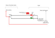
The DC power supply will have a positive and negative connection regardless of voltage. Take the positive to the middle tab on each DPDT point switch (one side of the switch is free for this while the opposite side is used for the point motor operation). Linking all middle tabs together. From one end tab on the same row as the middle tab take a wire to to LED Anode lead *Anode" is Positive and on an LED its the longer lead). Do the same from the other ends switch tab to the other LED Anode lead for that point.
Connect together the two Cathode leads of the two LEDs and connect to one end of a resistor** then from the other end of the resistor connect to the power supplies Negative wire. Resistors are not polarity conscious and can be wires either way around.
If actual point moving indication is required then you will need an unused change-over set of contacts on the point motor. All wiring is the same but the motors switch is then wired as above instead of the toggle switch. Two wires would be needed from each motors switch back to the panel LEDs and a Positive feeds to all motors switches Common tab. Panel LEDs are wired as per above. Two wires from motors switch go each to the each LED Anode and the two LEDs Cathode are joined together and onto one end of a resistor etc.
** Resistors Ohm value for 12volt DC I would use a 1K (1000 Ohm) for average brightness and on 5v DC use a minimum 330R (330 Ohm). 1/4 watt in all cases.
The alternative to Standard LEDs and a series resistor is to use 'Voltage rated' LEDs e.g. 12volt or 5 volt etc. Then no resistor is needed.
So now toggle switch in one position illuminates LED 1 and in the other position LED 2 illuminates. Note these LEDs are not actually indicating that the point position and that its motor has moved. Only that the switch has moved.
If actual point moving indication is required then you will need an unused change-over set of contacts on the point motor. All wiring is the same but the motors switch is then wired as above instead of the toggle switch. Two wires would be need from each motors switch back to the panel LEDs and a Positive feeds to all motors switch Common tab. Panel LEDs are wired as per above. Two wires from motors switch go each to the LED Anode and LEDs Cathode are joined together and onto one end of a resistor etc.

Re: dpdt switches
Then you don't have sufficient operation switch terminals as y ou have SPDT switches which are fine for operation. If you're feeding a DC supply to the motors then you can tap off the two feed wires to the motor and use the motors return too and feed LEDs. But that depends on voltage being feed to the motors coils for resistor value?
Re: dpdt switches
So that's AC at 16v?
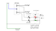
If so, it means two more things are needed to allow switch indications if your to use that supply for the LEDs. You will need diodes either in each feed lead from the switch to each LED (Option 1) or wired inverse across each LED (as option 2). You could put just one diode in the return LED wire, (not shown) but I prefer two of them them to be in each supply lead or inverse to the LED.
If using inverse diodes (option 2) the series resistor value is halved.
If possible use small 1N4148 diodes, but larger 1N4001 or 1N4002 are suitable too.

Who is online
Users browsing this forum: No registered users and 4 guests
