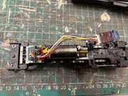
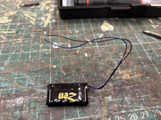
The engine is a Bachmann A2, fitted with a Hattons decoder. Please could some advise where I solder the two wires to fit a DCC Concepts stay alive capacitor. Thank you.
 << Click the Icon to go to my website << Click the Icon to go to my website << Click the Icon to go to my website
Users browsing this forum: No registered users and 2 guests